Interfaces
Cubis MSU User Manual 129
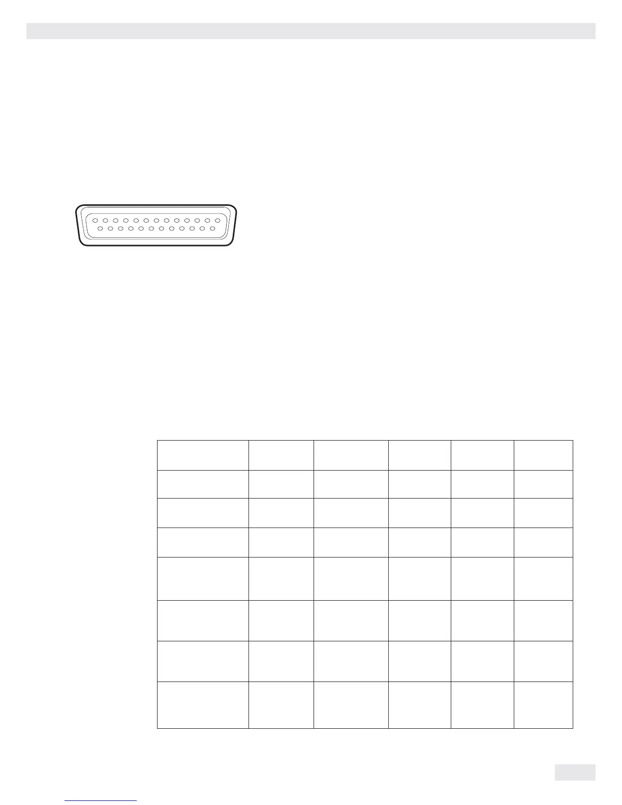
Pin Assignment Chart for Connecting Peripherals
Purpose: For Sartorius peripheral devices
Female Interface Connector: 25-pin D-Sub (DB25S) with screw connection
Required Male Connector (Recommended): 25-pin D-Sub, DB25S, with integrated shielded cable clamp and
shield plate assembly (Amp type 826 985-1C) and fastening screws (Amp type 164
868-1)
Pin assignment 25-pin socket, RS-232:
Pin 1: Signal ground Pin 14: Internal ground (GND)
Pin 2: Data output (TxD) Pin 15: Control input/output 1
2)
Pin 3: Data input (RxD) Pin 16: Control input/output 2
2)
Pin 4: Signal GND Pin 17: Control input/output 3
2)
Pin 5: Clear to send (CTS) Pin 18: Control input/output 4
2)
Pin 6: Not used Pin 19: Control input/output 5
2)
Pin 7: Internal ground (GND) Pin 20: Data terminal ready (DTR)
Pin 8: Internal ground (GND) Pin 21: Not used
Pin 9: Not used Pin 22: Not used
Pin 10: Not used Pin 23: Not used
Pin 11: + 12 V output Pin 24: Not used
Pin 12: Reset _ Out
1)
Pin 25: +5 V output
Pin 13: + 5 V output
1) = Peripherals restart
2) = Assignment of control inputs/outputs can be configured in each menu
(see below)
Control Inputs/Outputs
* Default assignment of input, otherwise configurable
** Assignment of output for checkweigher
 Loading...