Date Code 20010731 Installation 2-29
SEL-352-1, -2 Instruction Manual
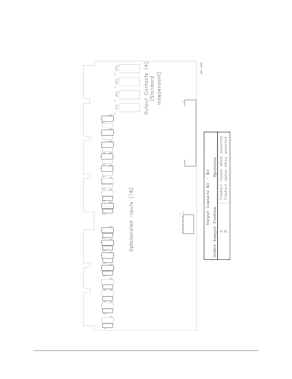
Configure the output contacts as “a” contacts or “b” contacts with solder jumpers. Figure 2.26
shows the location of the jumpers and explains the jumper position. Contacts are factory
configured as “a” contacts.
Figure 2.26: Interface Board 4 Component Layout


 To Next Page