3-62 Protection Functions Date Code 20080110
SEL-387E Instruction Manual
For volts/hertz tripping the relay provides a time-integrating element with a settable operating
characteristic. You can set the element to operate as an inverse-time element; a user-defined
curve element (using the SEL-5806 PC Software); a composite element with an inverse-time
characteristic and a definite-time characteristic; or as a dual-level, definite-time element. In any
case, the element provides a linear reset characteristic with a settable reset time. This element
also is supervised by the 24TC torque-control setting.
The volts/hertz tripping element has a percent-travel operating characteristic similar to that
employed by an induction-disk time-overcurrent element. This characteristic coincides well with
the heating effect that overexcitation has on transformer components.
The element compares the three phase voltages and uses the highest of the values for the
volts/hertz magnitude calculations. The relay tracks the frequency over the range 40.1 to 65 Hz,
but only on the A-phase voltage.
Volts/hertz tripping elements are usually used to trip the transformer breaker. Volts/hertz logic is
discussed in the following section. For more detail and for examples of tripping SEL
OGIC
control
equations, refer to
Section 4: Control Logic.
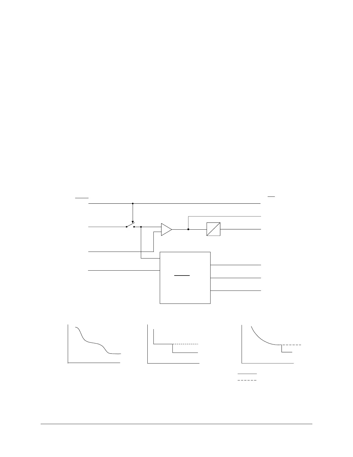
Figure 3.38, following, diagrams the logic of the volts/hertz elements.
DWG: M387E059
+
-
24D1D
0
Volts/Hertz Element
Curve Timing and
Reset Timing
Settings
24D2P1
24D1
24D1T
24C2
24C2T
24CR
(V/
Hz)
t
V/Hz
24D2P1
24D2P2
24IP
24D2D2
24CCS=DD
24IP
24D2P2
t
V/Hz
24CCS=ID
Relay
Word
Bits
24TC
Switch
closed
when
24TC=1
24D2D2
24CCS
V/Hz
t
24CCS=U
24D2D1
24TC
Setting
24D1P
24CCS=I
24D2D1
24IP
24IC
24ITD
24D2P2
24D2D2
SEL
OGIC
24CR
Figure 3.38: Volts/Hertz Element Logic Diagram