4-6 Control Logic Date Code 20080110
SEL-387E Instruction Manual
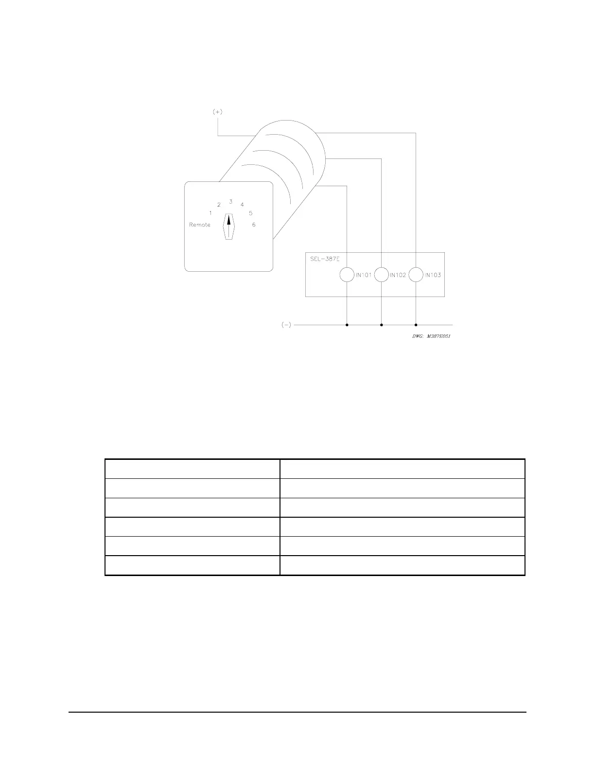
inputs IN101, IN102, and IN103 on the relay are connected to a rotating selector switch in
Figure 4.2.
Figure 4.2: Rotating Selector Switch for Active Setting Group Selection
The selector switch has multiple internal contacts arranged to assert inputs IN101, IN102, and
IN103, dependent on the switch position. As shown in
Table 4.3, as the selector switch is moved
from one position to another, a different setting group is activated. The logic in
Table 4.2 is
implemented in the SEL
OGIC
control equation settings in Table 4.3.
Table 4.3: SEL
OGIC
Control Equation Settings for Rotating Selector Switch
SS1 = !IN103 * !IN102 * IN101 = NOT(IN103) * NOT(IN102) * IN101
SS2 = !IN103 * IN102 * !IN101 = NOT(IN103) * IN102 * NOT(IN101)
SS3 = !IN103 * IN102 * IN101 = NOT(IN103) * IN102 * IN101
SS4 = IN103 * !IN102 * !IN101 = IN103 * NOT(IN102) * NOT(IN101)
SS5 = IN103 * !IN102 * IN101 = IN103 * NOT(IN102) * IN101
SS6 = IN103 * IN102 * !IN101 = IN103 * IN102 * NOT(IN101)
The REMOTE switch position de-energizes all relay inputs, thus placing all of the SSn variables
in state 0. With none of the SSn variables asserted, the GRO n command, or the GROUP
pushbutton on the front panel, can be used to change the setting group. With the switch in any
other position, 1 through 6, the GRO n and GROUP functions will not effect a group change.
The setting TGR, the group change delay setting, should be set long enough so that the switch, as
it is rotated from one position to another, will not remain at any intermediate position long
enough to make any setting group change. For example, in rotating from position 1 to position 5,
the switch must pass through positions 2, 3, and 4. It should not remain in 2, 3, or 4 for longer