4-10 Control Logic Date Code 20080110
SEL-387E Instruction Manual
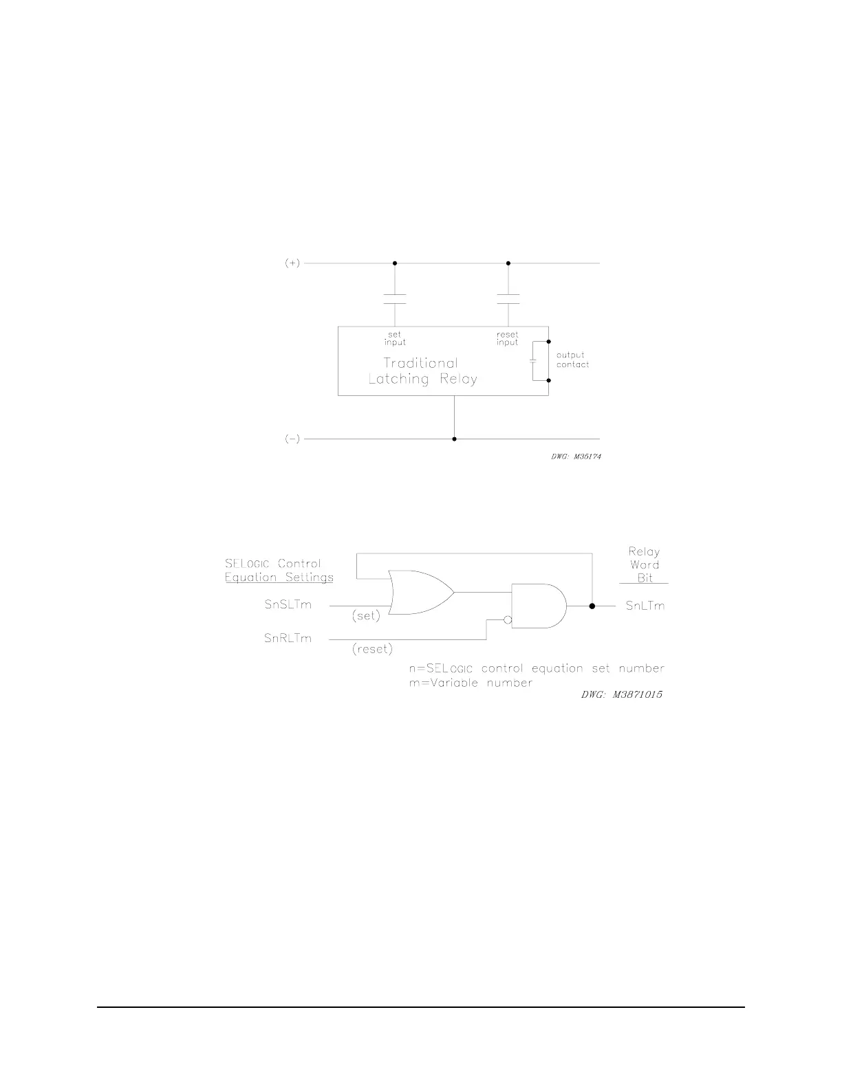
voltage to maintain their output contact state. For example, if a latching relay output contact is
closed and then dc voltage is lost to the panel, the latching relay output contact remains closed.
The state of a traditional latching relay output contact is changed by pulsing the latching relay
inputs (see
Figure 4.4). Pulse the set input to close (“set”) the latching relay output contact.
Pulse the reset input to open (“reset”) the latching relay output contact. Often the external
contacts wired to the latching relay inputs are from remote control equipment (e.g., SCADA,
RTU, etc.).
Figure 4.4: Traditional Latching Relay
The latch bits in the SEL-387E Relay provide latching relay type functions (
Figure 4.5).
Figure 4.5: Latch Bits in SEL
OGIC
Control Equation Sets
The output of the latch bit logic is a Relay Word bit SnLTm. The bit is set by application of
SnSLTm (Set LaTch bit), and reset by the application of SnRLTm (Reset LaTch bit). The
Set/Reset values come from the logical state of the SEL
OGIC
control equations stored for these
two settings. These latch bits may be used in SEL
OGIC
control equations, wherever a latching
function is required.
If setting SnSLTm (Set) asserts to logical 1, latch bit SnLTm asserts to logical 1 and seals itself
via the OR and AND gates. If setting SnRLTm (Reset) asserts to logical 1, the seal-in is broken
and latch bit SnLTm deasserts to logical 0. If both settings SnSLTm and SnRLTm assert to
logical 1, setting SnRLTm (Reset) takes precedence, and latch bit SnLTm deasserts to logical 0.