Date Code 20080110 Metering and Monitoring 5-21
SEL-387E Instruction Manual
If you type
N
or
n
, the relay displays:
Canceled
and aborts the command.
If you type
Y
or
y
, the relay displays:
Rebooting the relay
The relay then restarts (just like powering down and then powering up the relay), and all
diagnostics are rerun before the relay is enabled.
The quantities shown in the STATUS report are discussed below. The applicable limits for
warning or failure of each self-test are summarized in
Table 5.3.
When the optional Ethernet ports are not installed, all Ethernet port (communications card) self-
check statuses indicate N/A, except BOARD, which indicates ABSENT.
The
<STATUS>
button on the front-panel interface can also be used to access the information in
the report. See
Section 8: Front-Panel Operation
.
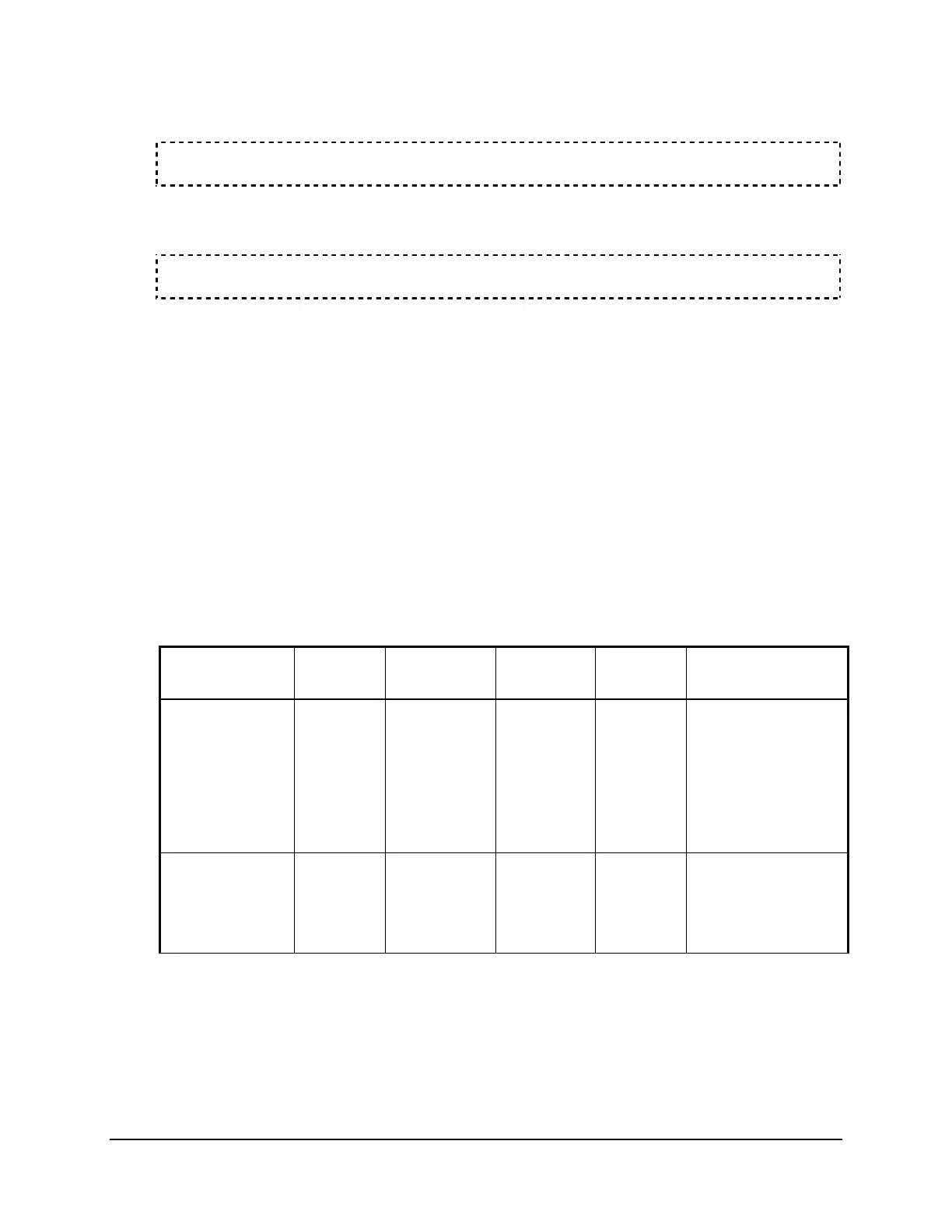
Table 5.3 summarizes the limits for issuing warning or failure alarms during self-testing. The
power supply and temperature alarms list the values below or above which the stated alarm is
issued.
Table 5.3: Self-Test Alarm Limits
Self-Test Condition Limit Protection
Disabled
ALARM
Output
Description
IAW1, IBW1,
ICW1, IAW2,
IBW2, ICW2,
IAW3, IBW3,
ICW3, VAWX,
VBWX, VCWX,
Offset
Warning 30 mV No Pulsed Periodically
measures the dc
offset at each of the
input channels.
+5 V PS Warning
Failure
+4.80 V
+5.20 V
+4.65 V
+5.40 V
No
Yes
Pulsed
Latched
Periodically
measures the +5 V
power supply