7-4 Communications Date Code 20080110
SEL-387E Instruction Manual
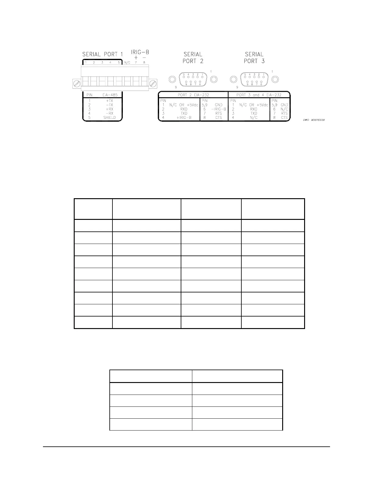
(female chassis connectors as viewed from outside panel)
Figure 7.1: SEL-387E Relay Serial Port Connectors
Connector pinout for the EIA-232 ports and terminal functions for the EIA-485 port are as
shown in
Table 7.2 and Table 7.3, respectively, with descriptions as shown in Table 7.4.
Table 7.2: Pinout Functions for EIA-232 Serial Ports 2, 3, and F
Pin
Number
Port 2 Rear EIA-232
with IRIG-B
Port 3 Rear
EIA-232
Port 4 Front
EIA-232
1 N/C or +5 Vdc
a
N/C or +5 Vdc
a
N/C
2 RXD (In) RXD (In) RXD (In)
3 TXD (Out) TXD (Out) TXD (Out)
4 N/C or +IRIG-B
a
N/C N/C
5 GND GND GND
6 N/C or –IRIG-B
a
N/C N/C
7 RTS (Out) RTS (Out) RTS (Out)
8 CTS (In) CTS (In) CTS (In)
9 GND GND GND
a
Install a jumper to use the 5 V connection, and remove a solder jumper to disable
the IRIG-B input. See Section 2: Installation for more information.
Table 7.3: Terminal Functions for EIA-485 Serial Port 1
Terminal Function
1 +TX (Out)
2 –TX (Out)
3 +RX (In)
4 –RX (In)