Section 08 ENGINE MANAGEMENT (4-TEC)
Subsection 02 (COMPONENT INSPECTION AND ADJUSTMENT)
1
R1503motr200A
TYPICAL
1. Wiring harness
Remove complete wiring harness.
Installation
First connect the ECM connector A and fix the
harness on the wiring support with a locking tie.
1
R1503motr201A
1. Locking tie
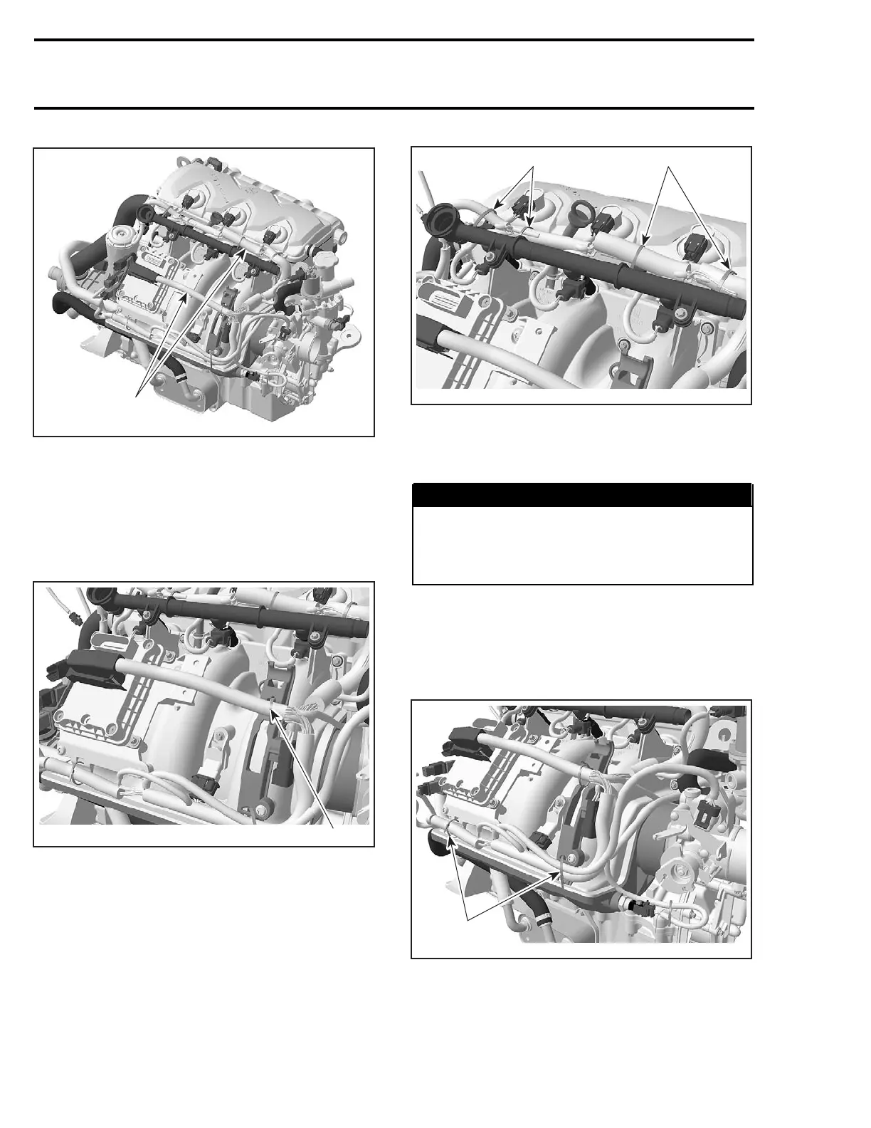
Lead the cable bundle with the injector and igni-
tion coil connectors to the fuel rail and fix it also
by using 4 locking ties.
1
R1503motr202A
1
1. Locking ties
Connect the fuel injectors, ignition coils, CAPS,
CTS and EGTS to the wiring harness.
WARNING
Pay attention not to mix injectors or ignition
coils wires between cylinders. The location
of the splice connectors indicate which cylin-
der wires belong to.
Install the engine connector on the appropriate
bracket on the wiring support.
Then fix the other bundle on the appropriate sup-
ports on the wiring support and the ECM bracket
with locking ties.
1
R1503motr203A
TYPICAL
1. Locking ties
Connect the CPS, KS, OPS, and the MAPS to the
wiring harness.
420 smr2004-Complete Line Up
 Loading...


