Section 13 PROPULSION
Subsection 02 (DRIVE SYSTEM)
4-TEC Models
Discard damper no. 25 to install a new one.
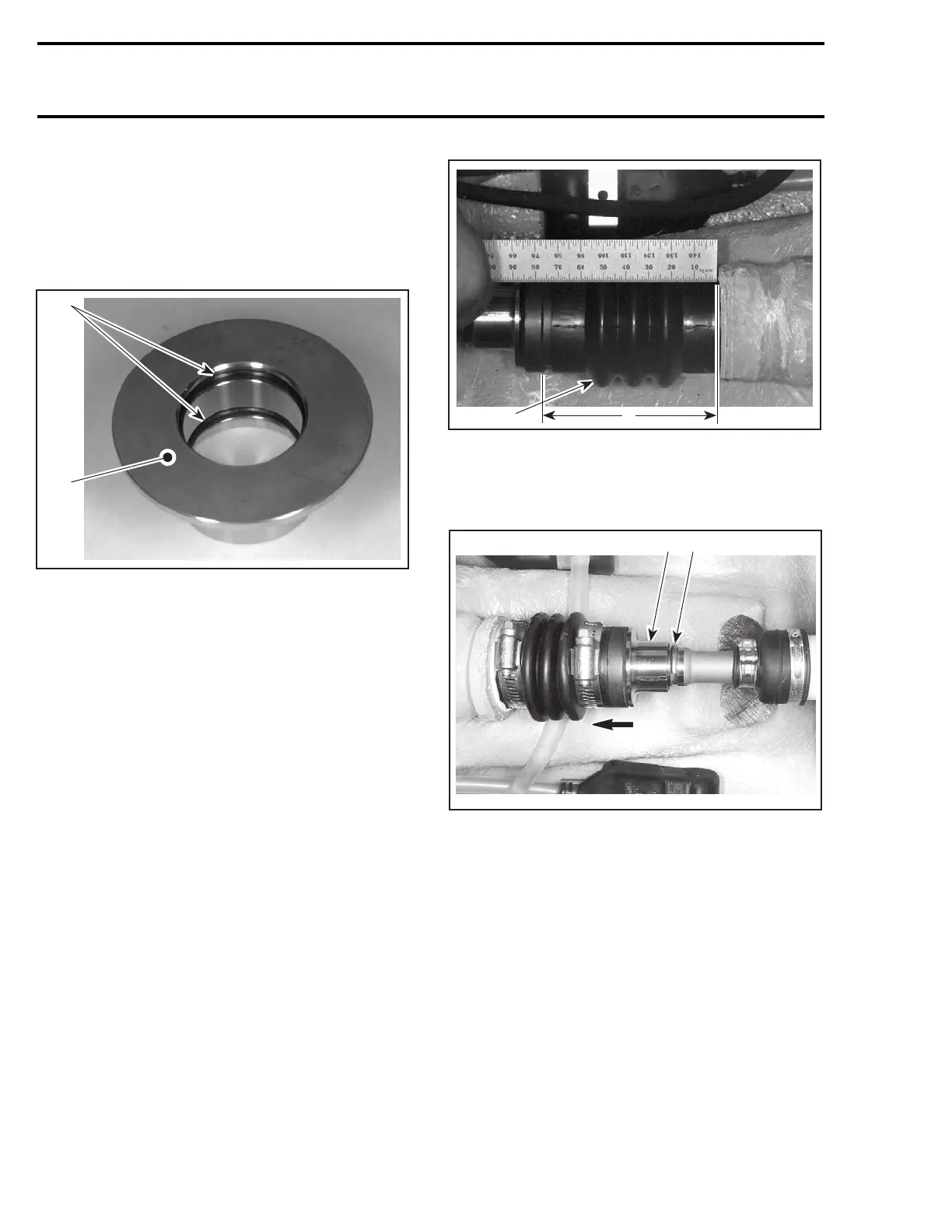
Floating Ring and O-Ring
Inspect condition of O-rings no. 7 and floating ring
contact surface.
F01I0GA
1
2
1. O-rings
2. Floating ring contact surface
PTO Seal
4-TEC Models
Discard both O-rings no. 26 and install new ones.
Inspect PTO seal assembly. Refer to PTO HOUS-
ING/MAGNETO section.
Boot
Inspect the condition of boot. If there is any dam-
age or evidence of wear, replace it.
All Models except 4-TEC Models
To verify the preload of the boot no. 10,proceed
as follows:
NOTE: To verify the boot preload and free length,
jet pump and drive shaft must be installed.
Measure boot length when normally installed on
drive shaft. Ensure circlip no. 5 is properly in-
stalledintogroove.
F00J03A
1
A
1. Boot
A. Measure here
Push floating ring to compress boot; then, remove
circlip out of drive shaft groove.
F06I06A
1 2
1. Push floating ring
2. Remove circlip
Slidefloatingringfarenoughforwardinorderto
release it from carbon ring.
Measure boot free length.
Subtract the installed length measurement from
the free length measurement. A difference of
4mmto12mm(5/32into15/32in)shouldbe
obtained.
If the length is less than 4 mm (5/32 in), install a
spacer (P/N 293 250 017) between boot and thru
hull fitting.
664 smr2004-Complete Line Up
 Loading...


