Section 13 PROPULSION
Subsection 04 (VARIABLE TRIM SYSTEM)
XP DI Models
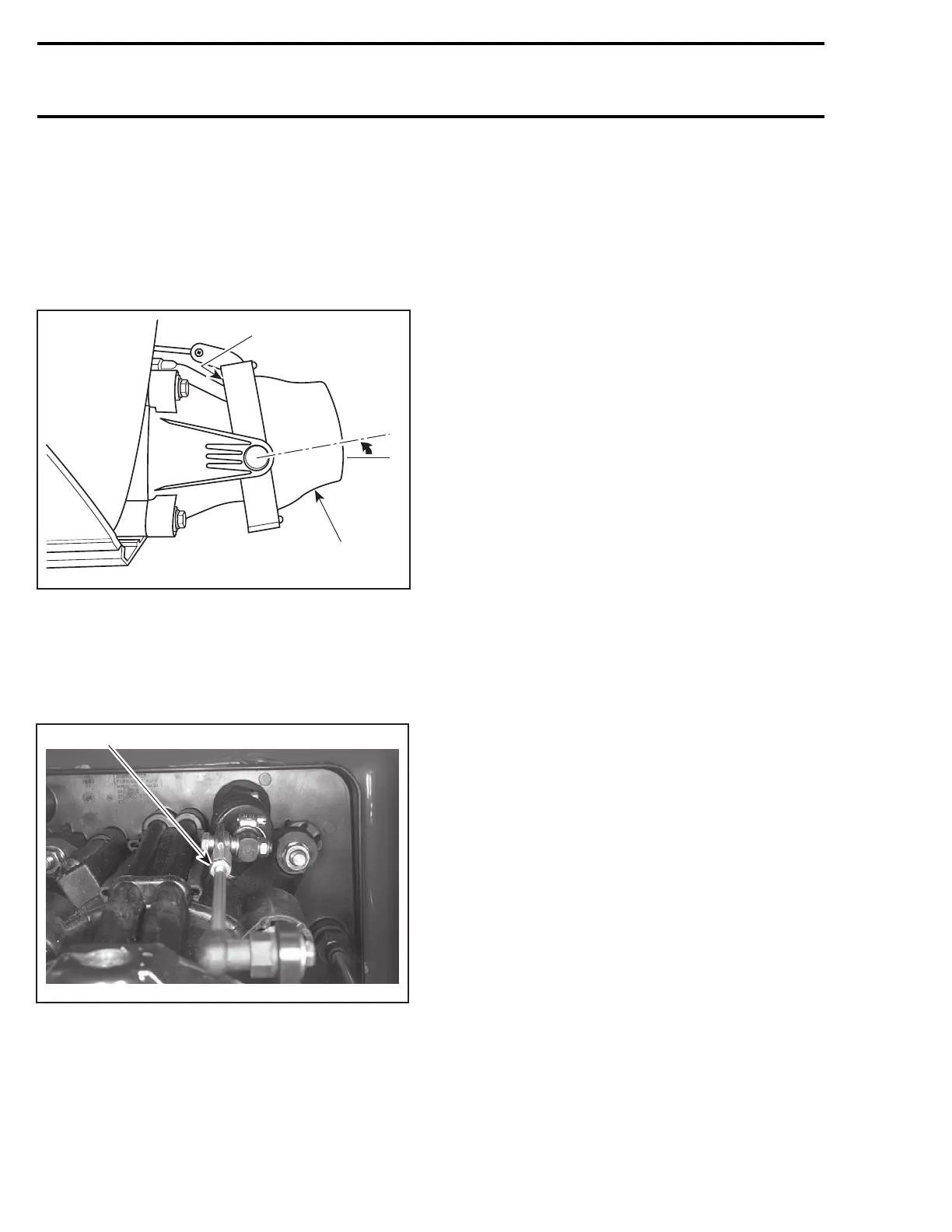
PushonVTSbuttonuppositionuntilmotorstops.
Whenthenozzleisup(8°), nozzle edge must not
interfere with venturi (there should be a gap of
1 mm (.039 in)).
NOTE: Install safety lanyard to be able to position
VTS.
F01J3IA
1
2
8°
1. No interference
2. Nozzle up
If an adjustment is necessary, loosen jam nut
no. 16 of VTS rod no. 1. Turn adjustment nut of
VTS rod to obtain the desired gap between trim
ring and venturi.
F06J01A
1
TYPICAL
1. Turn adjustment nut of VTS rod
Tighten jam nut of VTS rod to 2.5 N•m(23lbf•in)
when adjustment is completed.
684 smr2004-Complete Line Up
 Loading...


