HF Series Generators
Configuration
CF-1018R3
5
1.2 BASIC CONFIGURATION OF GENERATOR BOARDS
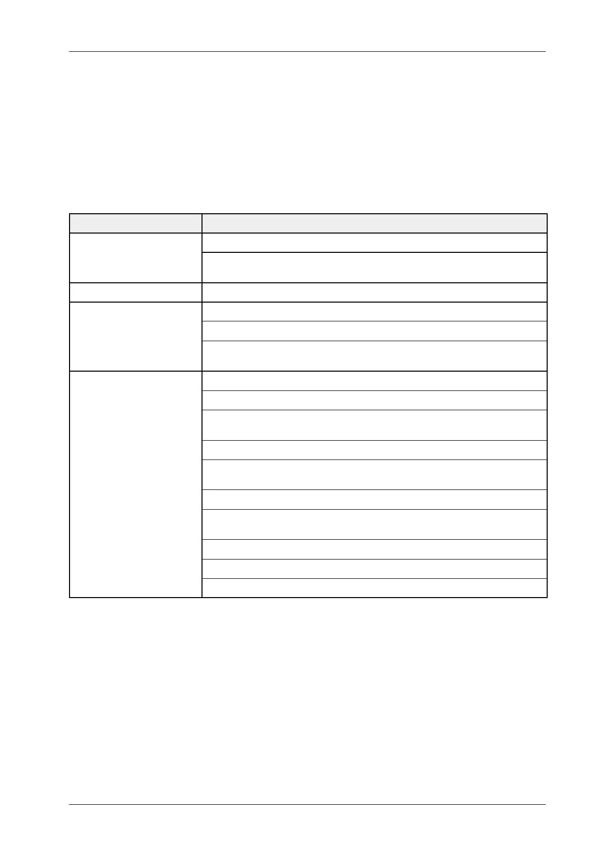
The following Jumpers are factory set or removed to configure the Generator
Boards according to the customer order. Check the jumper positions in the
Generator Boards.
GENERATOR BOARDS JUMPERS POSITION
JP1andJP2in“2”
HT CONTROLLER
JP3, JP5 and JP6 in “2” and JP4 in “1” : for Compact Generators.
JP3, JP5 and JP6 in “1” and JP4 in “2” : for Vertical Generators.
FILAMENT CONTROL JP1in“A”
W1 in “2--3”
W2 in “1--2”
W3 to W10 in “A” : for positive High Voltage supply for Ion Chamber
W3 to W10 in “B” : for negative High Voltage supply for Photomultiplier Tube
JP1, JP2 and JP3 in “B” (soldered)
JP4 in “B” (Cam-Sync)
JP5 in “B” : Standard
JP5 in “C” : for R&F / DSI Generators with AEC Control Board A3012--02/05
JP6 in “A” (soldered)
Connector J8 configured for RS232 so: JP9, JP10 and JP11 in “A”.
JP7, JP8, JP21 and JP22 do not matter jumpers position
JP12 removed
JP13 installed (set) : if AEC Control Board A3012--xx is installed
JP13 removed : if AEC Control Board A3012--xx is not installed
JP14 installed (soldered)
JP15, JP16, JP17 and JP18 removed
JP19 in “A” (soldered)