HF Series Generators
Installation
IN-1052R0
15
SECTION 3 CABLE CONNECTIONS
This section provides the information necessary to connect the Generator
Cables with the system and options.
For more information about electrical requirements and cable
connections, refer to the “Pre-Installation” document and
Section 5 “System Interconnections” at the end of this document.
Identification of some terminal connections (TB, TS), boards, etc...
along with this document (text and schematics) may have a prefix
number which indicates the module number in the equipment.
(a.e. TS2 as 4TS2, 10TS2 or 11TS2).
Some safety devices such as the Safety Switch / Emergency Switch, Warning
Light, and Door Interlock Switch are supplied and installed by the customer.
Verify that safety devices have been properly installed and routed during the
Pre-Installation procedure.
3.1 CABLE ROUTING INSIDE GENERATOR CABINET
3.1.1 GENERAL CABLE ROUTING
1. Before connecting the Interconnection cables within the Generator
Cabinet, cables must be first connected to each Device (Positioner,
Tables, Buckys, etc.) and routed through the raceways. Remove the
ferrite blocks of the cables (factory clamped) when it is required to carry
out a correct routing, then re-install the ferrite blocks where they originally
were around cables.
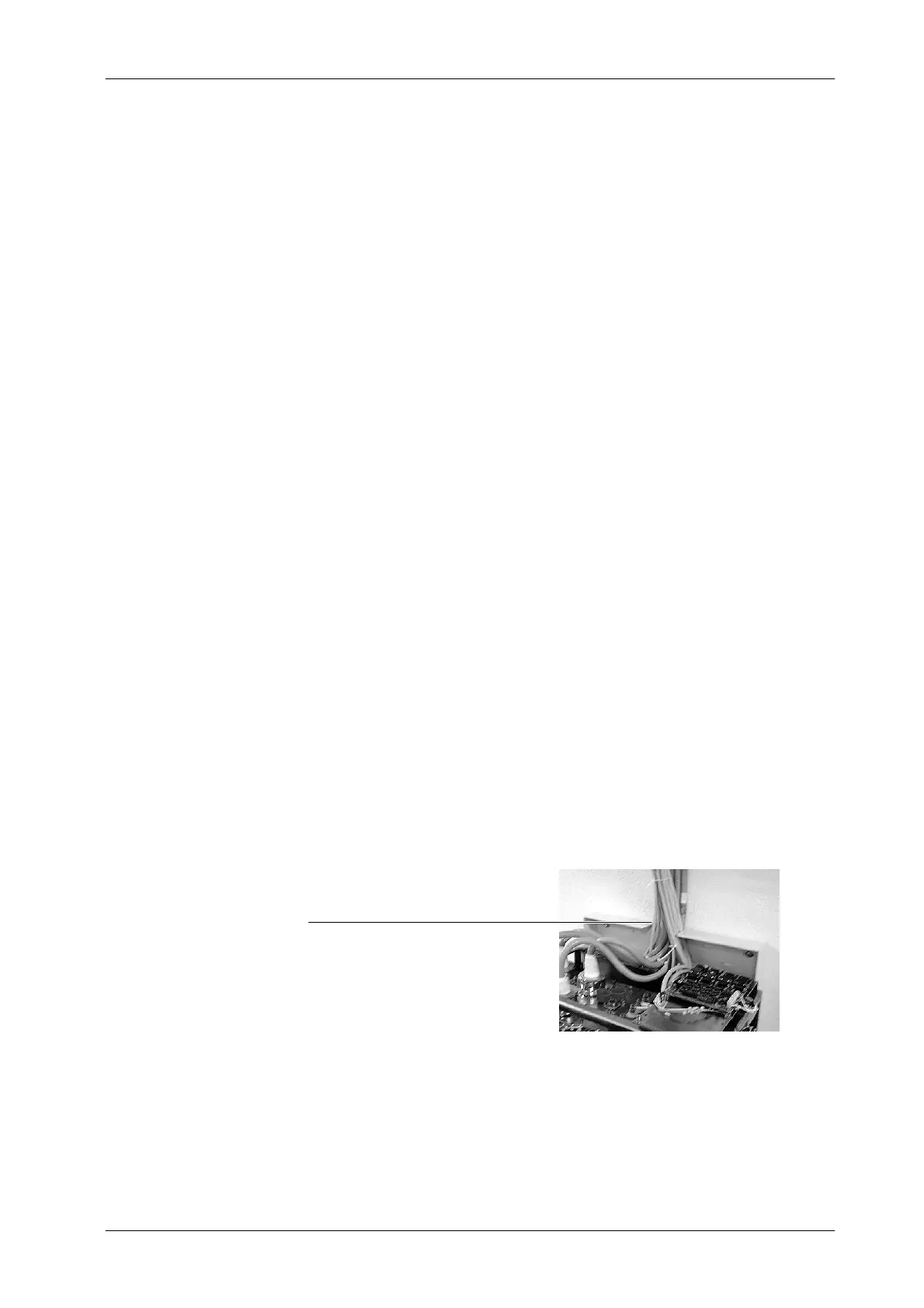
Cables Entrance (upper side of Wall Support
2. Inside the Generator Cabinet, all Interconnection cables must be routed
over the Fastening Bar (upper rear bar) of the Cabinet Frame minding the
upper Cable Outlet at the rear side of the C abinet Cover. (Refer to
Illustration 3 -1).
Note .
Note .