HF Series Generators
Pre-Installation
PI-1005R3
19
3.9 INTERCONNECTION AND GROUNDING REQUIREMENTS
Every installation must be provided with a main line disconnect device
(thermomagnetic breaker) and the remote disconnect devices required at all
Consoles that are not located next to the line safety switch. (For more
information about interconnection and grounding refer to “Installation”
document).
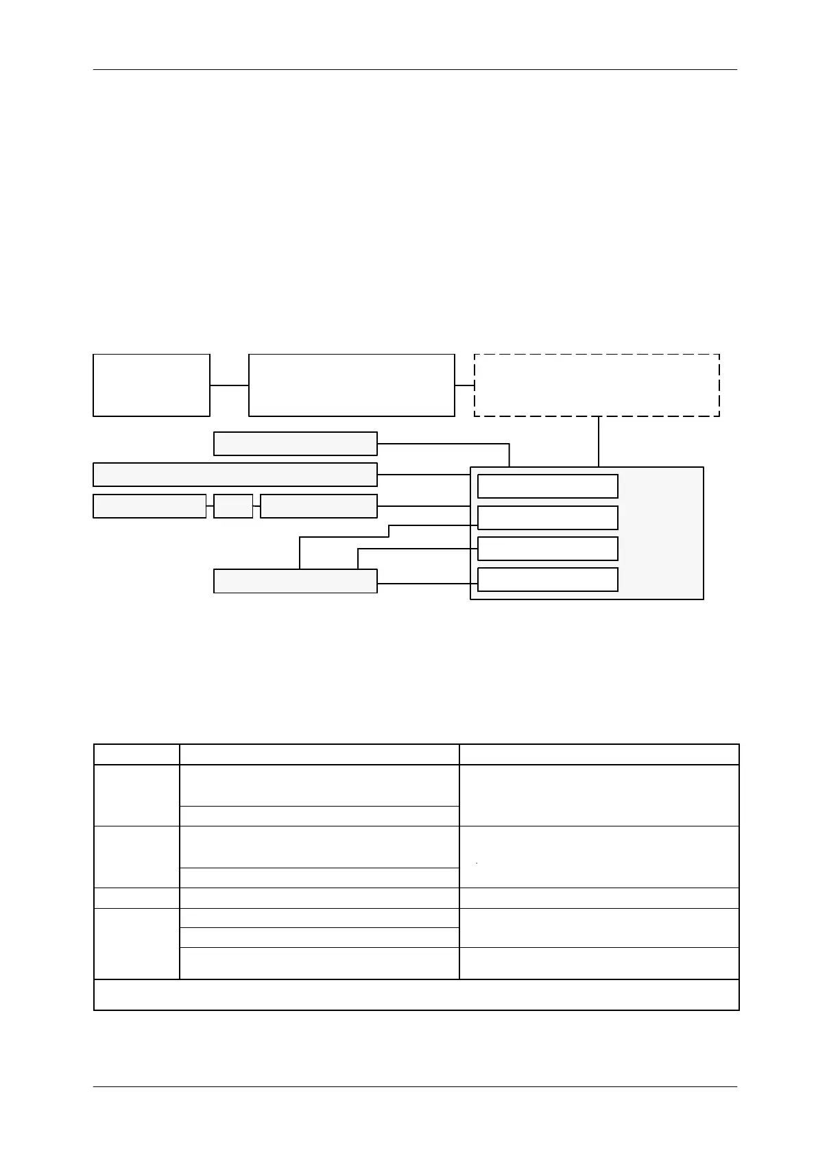
Illustration 3-1
Interconnection Block Diagram for LINE POWERED GENERATORS
DISTRIBUTION
TRANSFORMER
(Hospital, etc.)
ROOM ELECTRICAL CABINET WITH
LINE SAFETY SWITCH
(Provided by customer)
1
GENERATOR
CABINET
2
SERIAL CONSOLE or TOUCH SCREEN CONSOLE (TPC)
Serial Comm.
HV Cables
HV TRANSFORMER
POWER MODULE
LF-RAC (LS)
LV-DRAC (HS)
or
X-RAY TUBE
4
4
or
CONTROL CONSOLE
3
TOUCH SCREEN PC PC INTERFACE BOX
or
Serial Comm.
or
AUX. BOOST TRANSFORMER
WHEN POWER LINES IS 210 VAC OR BELOW OR FOR
80 kW GENERATORS WITH LINES AT 400 / 415 / 440 VAC
(Provided by customer)
For Serial Generators (RS232 / RS422): Console CPUs are located
inside the Generator Cabinet and Interconnections are factory made.
Only one cable (serial communication) from J5 of the Generator Cabinet
should be connected to the Serial Console, Touch Screen Console or
PC Interface Box.
CABLE RUN FUNCTION REMARKS
1
Single or Three Phase Power.
(1φ : 230 / 240 VAC)
(3φ : 230 / 240 VAC or 400 / 415 / 440 / 480 VAC)
Connect to Room Electrical Cabinet according to the indicated
electrical re
uirements. Cus
o
e
su
ed.
Ground.
.
.
2
Single or Three Phase Power.
(1φ : 230 / 240 VAC)
(3φ : 230 / 240 VAC or 400 / 415 / 440 / 480 VAC)
Connect to Generator according to the indicated electrical
requirements. Install an Auxiliar Boost Transformer when it is
Ground.
required. Customer supplied.
3 Control Signals and Ground Cable quantity depends on the options installed (AEC, etc.)
Stator Supply.
Ground.
P
o
ded w
-
a
u
e.
Generator provided with LV-DRAC requires a shielded stator
cable. (Refer to “Installation” document).
Field supplied.
NOTES: -- For wire s ize refer to Section 3.4. Consult to Local Standards for feeder and ground wire size requirements.
-- The system power ground point is located in the Generator Cabinet.
Note .