HF Series Generators
Installation
IN-1052R0
31
3.4.4 WARNING LIGHT SIGNAL
Room Warning Lamp(s) can be externally powered, or internally by the Terminal
Block 3TS1. Room Lamp(s) must be connected through the Terminal Block
3TS1-47 and 3TS1-48 (internal relay on Interface Control Board) to enable the
Generator switches On/Off the Room Warning Lamps. (Refer to Section 5.2 --
I/F-008).
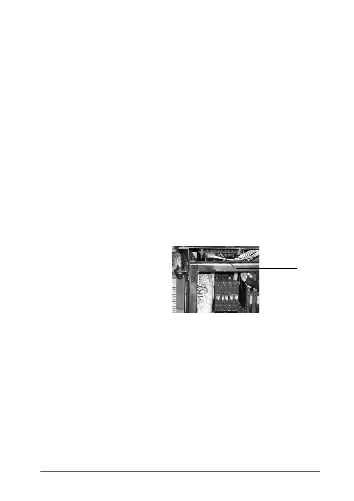
3.4.5 COLLIMATOR LAMP AND SYSTEM LOCKS
The Generator can supply power to the Manual Collimator Lamp and System
Locks (Table, Vertical Bucky, etc.)
Connect wires from the Collimator Lamp to Terminal Block TB7-3 (24 VAC) and
TB7-4 (0 VAC) of the Lock Board.
Connect wires from the Locks to Terminal Block TB7-5 (+24 VDC) and TB7-6
(0 VDC) of the Lock Board.
Lock Board
When required, voltages (VAC and VDC) on TB7 can be changed
by connecting their respective wires to the other available
terminals on the Input Transformer 6T2. (Refer to Schematics
543020XX).
Note .