HF Series Generators
T roubleshooting
TR-1005R4
5
SECTION 2 GENERAL PROCEDURES
2.1 LOW DC VOLTAGE POWER SUPPLY TEST
The Generator operates from a Low DC Voltage Power Supply located in the
Front Panel (MOD. 3) of the Generator Cabinet. (Refer to Illustration 2-1).
T urn the Generator ON and with a Digital Multimeter measure between:
• P2-3 (+) and P2-4 on the HT Controller Board. Check that the voltage
at this point is +5 ±0.2 VDC. If required, adjust voltage with the +5 VDC
Adjustment Potentiometer on the Power Supply Board.
• P2-2 (+) and P2-4 on the HT Controller Board. Check that the voltage
at this point is +12 ±0.1 VDC. If required, adjust voltage with the
+12 VDC Adjustment Potentiometer on the Power Supply Board.
• P2-1 (--) and P2-4 on the HT Controller Board. Check that the voltage
at this point is --12 ±0.1 VDC (this voltage must be --12.7 ±0.1 VDC if
the Console is provided with a Graphic Display). If required, adjust
voltage with the --12 VDC Adjustment Potentiometer on the Power
Supply Board.
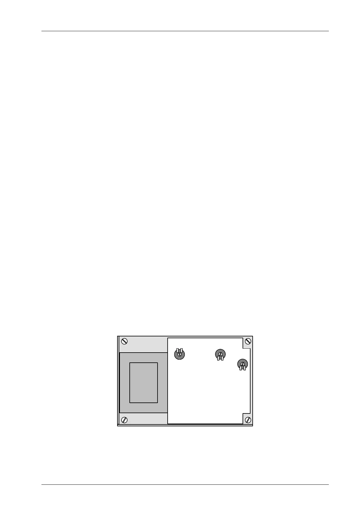
Illustration 2-1
Power Supply in the Front Panel
R26
ADJ. +12 VDC
POWER SUPPLY BOARD
R25
ADJ. -- 12 VDC
R12
ADJ. +5 VDC