HF Series Generators
Calibration
CA-1036R2
54
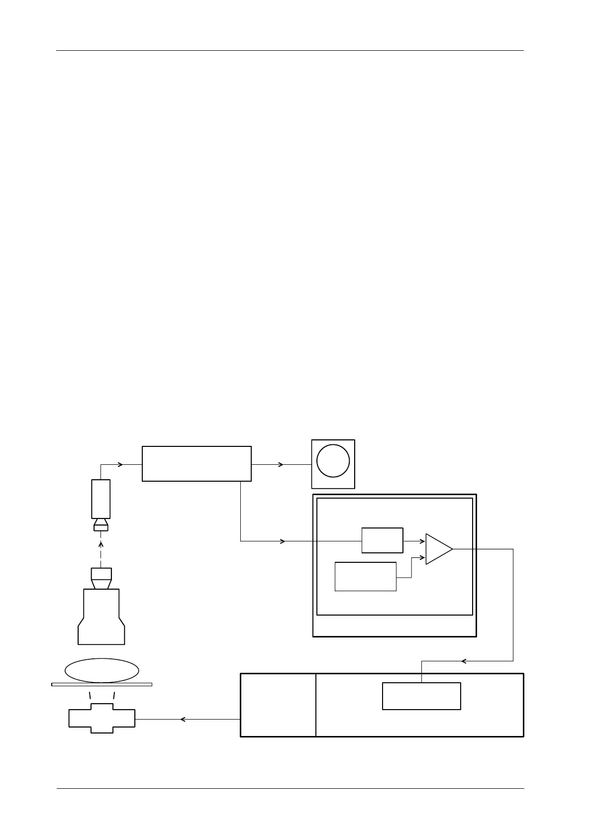
2.8.2 ABC SYSTEM WITH TV CAMERA
The ABC can be performed with an Analogic Signal Output (ABC OUT)
proportional to the brightness or with the Composite Video Signal Output from
the TV Camera.
The “ABC OUT” signal from the TV Camera is compatible with the Generator
when the range is from 0 VDC (dark image) to 10 VDC (bright image) and the
Optimum Brightness is achieved at around 6 VDC.
When a TV Camera without a direct “ABC OUT” signal is used, the C omposite
Video signal (which amplitude is proportional to the image tube output
brightness) is sent to an RF Adaptation Board where it is transformed into an
“ABC OUT” analogic signal. In this case, the brightness level is taken from a
rectangular window from the center of the raster. (Refer to Illustration 2-7).
This analogic signal in the AEC Control Board (“PT Input” in Board
A3012--x1/x2/x5 and “ABC OUT” in Board A3012--x6/x7/x9) is filtered, and
compared to a window reference. Brightness error at the comparator output is
sent as “kV Up” and “kV Down” to the Generator where is used to drive the fluoro
kV control. The closed-loop operation requires more or less brightness thru “kV
Up” and “kV Down” demand signals respectively. Patient entrance dose is
automatically varied so that cons tant image tube output brightness is
maintained.
Illustration 2-7
ABC System for TV Camera
FILTER
R5 -- C11
WINDOW ADJ.
R11 -- R14
U8
MONITOR
LIGHT
TV
CAMERA
IMAGE
TUBE
PT INPUT
(Brightness signal)
PATIENT
X-RAY TABLE
X-RAY TUBE
CONTROL CONSOLE
AEC CONTROL PCB
WINDOW
COMPARATOR
POWER MODULE
HT CONTROL PCB
HV
TRANSFORMER
KVUP&KVDWN
RF ADAPTATION BOARD
VIDEO OUTVIDEO IN
ABC OUT