HF Series Generators
Calibration
CA-1036R2
55
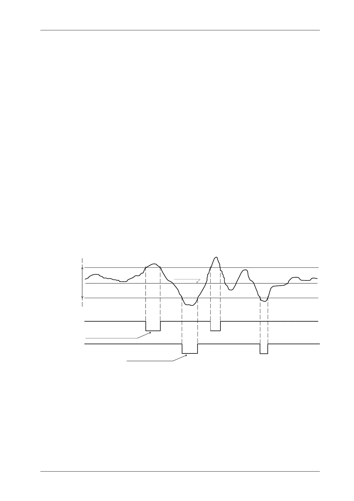
The optimum brightness level in ABC mode is set by adjusting the gain at R27
on the RF Adaptation Board. The “ABC OUT” signal requires an input range
from 0 to +10 VDC (the stabilized value will be between 5 and 7 VDC).
Window reference could be adjusted first to set mid-way the brightness level (+6
VDC), and second to increase or decrease the range of response and sensitivity
of the kV control to input variations (brightness changes). If oscillation occurs
during ABC fluoro exposure, increase the dead zone by adjusting R11 and R14
on the AEC Control Board. (Refer to Illustration 2-8 for ABC waveforms)
For system interface, refer to RF Adaptation Board. Adjust ABC System
according to the following procedures.
Illustration 2-8
ABC Waveforms in AEC Control Board
Command to drive
thefluorokVpUP
High Logic
Low
Logic
Command to drive
thefluorokVpDOWN
UP PT reference (R14)
DWN PT reference (R11)
Brightness level
(Gain adj.)
ABC IN
(U8--8)
--kV Down (J1--19)
-- k V U P ( J 1 -- 6 )
window reference