HF Series Generators
Installation
IN-1052R0
33
3.4.8 ION CHAMBERS (OPTIONAL)
The “AEC Control Board” (A3012-XX) must be installed on the ATP Console
CPU Board before installing the Ion Chamber(s). The “AEC Adaptation Board”
(A3263-03) is also required. (Refer to the “Ion Chamber” Service Manuals).
Perform the following tasks in the order described:
The Generator is only compatible with Ion Chambers that output
a positive ramp.
1. If an Ion Chamber requires High Voltage (200 to 500 VDC), the Generator
must include an Interface Control Board (version A3009-09/12) that
supplies this voltage.
The Interface Control Board must have Jumpers from W3 to W8 in “A”
position. This High Voltage is supplied through Terminal Block 3TS1-39
“PT SPLY” of the Generator Cabinet and sent with a w ire to TB1-9 of the
“AEC Adaptation Board”.
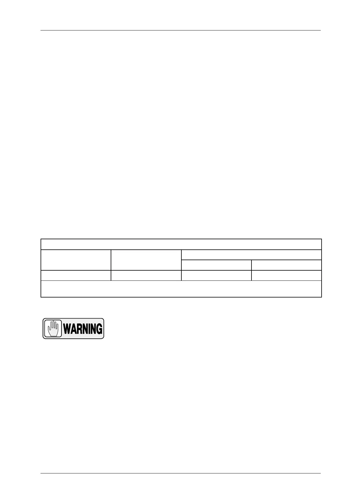
ION CHAMBERS WITH HIGH VOLTAGE
PHILIPS AMPLIMAT
GE B
M-CGR
AMP-Phenolic Connector DB 15 Connector
300 VDC 230 VDC 500 VDC 400 VDC
Notes: -- If the System included both GE and BVM-CGR Ion Chambers, Terminal TB1-9 must supply 270 VDC.
-- Philips Amplimat Ion Chambers can not be installed with GE or BVM-CGR Ion Chambers.
DO NOT CONNECT ANY ION CHAMBER TO THE
GENERATOR CABINET UNTIL HIGH VOLTAGE IS EITHER
VERIFIED OR ADJUSTED TO THE VALUES REQUIRED.
OTHER VOLTAGE COULD DAMAGE THE ION CHAMBERS.
Turn the Generator ON and verify voltage in TB1-9 according to the Ion
Chambers to be installed. If necessary, adjust the High Voltage at
Potentiometer R20 of the Interface Control Board. Turn the Generator
OFF after adjustment.
Note .