HF Series Generators
Calibration
CA-1036R2
33
ION CHAMBERS WITH DETECTOR GAIN SWITCHES
OR WITH POTENTIOMETER
1. Set the Detector Gain switches (or gain potentiometer) of the Ion
Chamber to mid range (refer to Ion Chamber documentation ). (If the Ion
Chamber is provided with the Generator, this adjustment is Factory set.)
The following tables indicate the switch position for the “Vacutec”Ion
Chamber (Factory set).
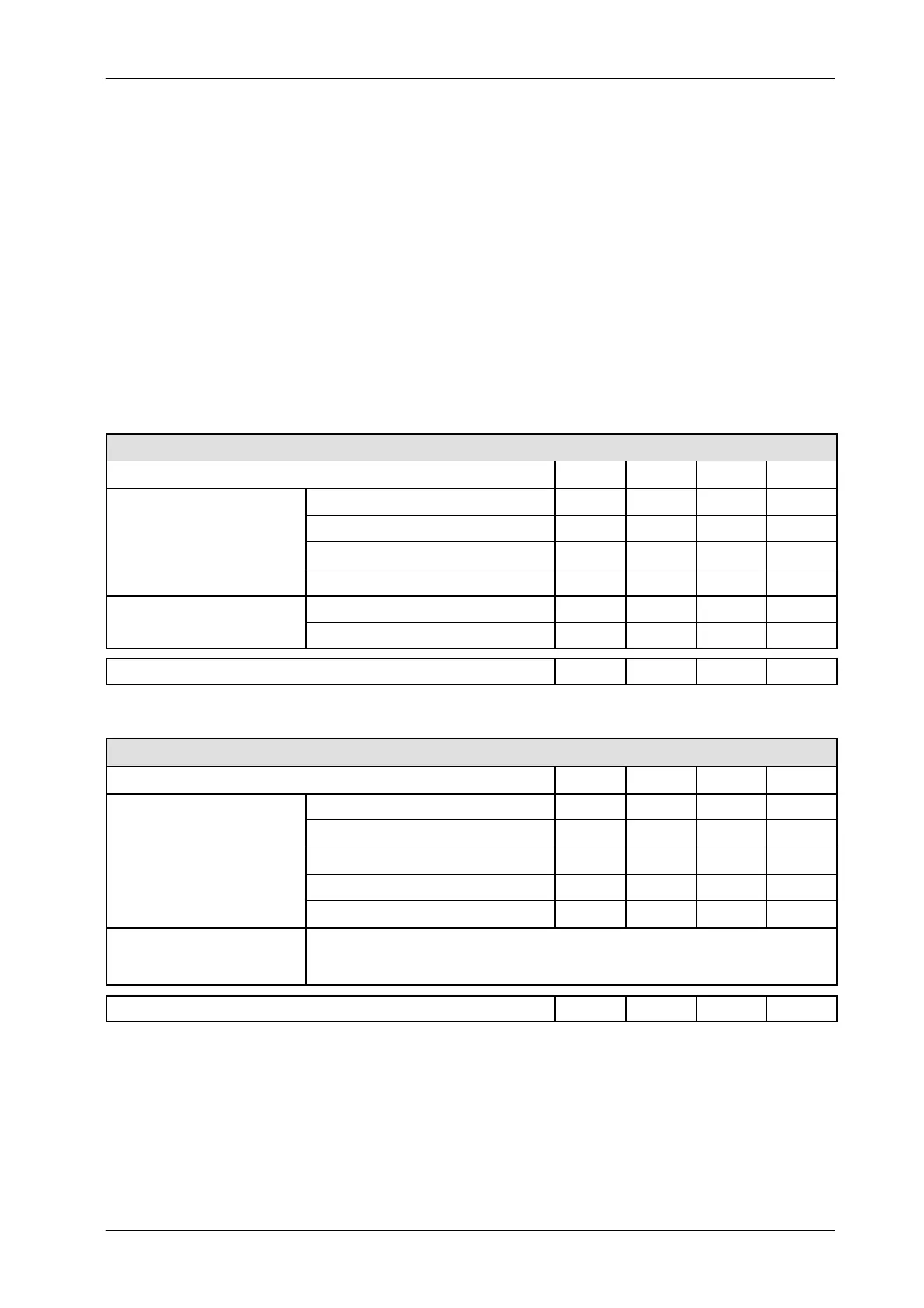
VACUTEC ION CHAMBER -- BAK 70 151 with Amplifier 70 901
SWITCH POSITION SW1 SW2 SW3 SW4
0.1 V / μGy (10 V≃ 100 μGy)
OFF OFF OFF
0.5 V / μGy (10 V≃ 20 μGy)
ON OFF OFF
G
IN
1V/μGy (10 V≃ 10 μGy)
OFF ON OFF
2V/μGy (10 V≃ 5 μGy)
OFF OFF ON
Positive ON
OUTPUT SIGN
L
Negative OFF
NORMAL FACTORY SELECTION: 1 V / μGy (10 V
≃
10 μGy) - Positive
OFF ON OFF ON
VACUTEC DIGITAL ION CHAMBER -- BAK 70 151 with Amplifier 70 902
SWITCH POSITION SW1 SW2 SW3 SW4
0.1 V / μGy (10 V≃ 100 μGy)
OFF OFF OFF OFF
0.5 V / μGy (10 V≃ 20 μGy)
OFF OFF OFF ON
GAIN
1V/μGy (10 V≃ 10 μGy)
OFF OFF ON OFF
2V/μGy (10 V≃ 5 μGy)
OFF ON OFF OFF
4V/μGy (10 V≃ 2.5 μGy)
ON OFF OFF OFF
OUTPUT SIGNAL
Positive or Negative polarity of the ramp signal is selected with a switch at the Ramp Module.
The Ramp Module is a 9-pin Sub-D connector plugged to the Ion Chamber cable.
Positive polarity of the ramp signal is factory set.
NORMAL FACTORY SELECTION: 1 V / μGy (10 V
≃
10 μGy) - Positive
OFF OFF ON OFF