HF Series Generators
Calibration
CA-1036R2
41
10. Repeat the above steps for all the Ion Chambers installed with the
Generator.
11. Exit from the “Go to User Mode” screen by pressing the “Manual
Calibration” button and exit from calibration mode.
12. Record all the values for the Memory Locations in the Data Book.
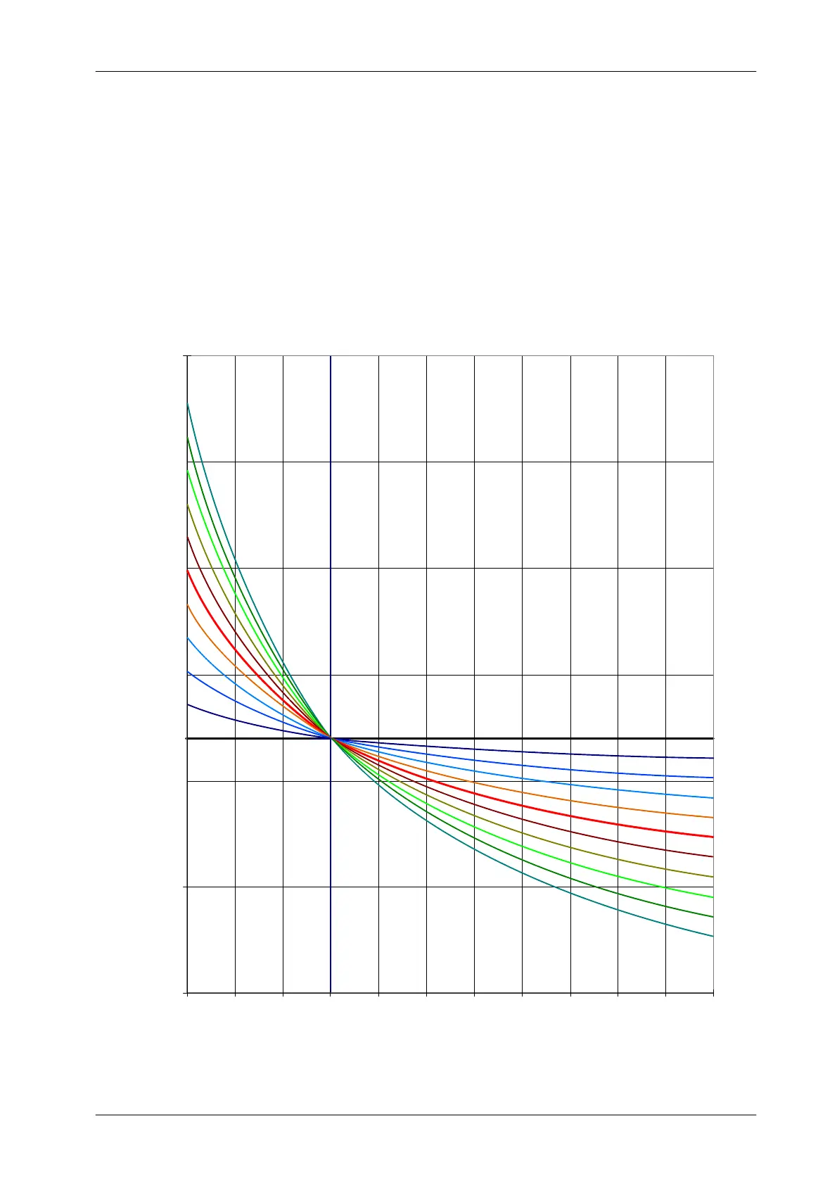
Illustration 2-3
AEC kV Tracking Curve
10
8
6
4
0
-- 1 0
-- 8
-- 6
-- 4
-- 2
2
40 50 60 9070 80 100 110 120 130 140 150
kV
0
70
50
100
150
200
250
-- 5 0
DAC OUTPUT in byte (8 Bit) (U3-2 of AEC Control Board)