HF Series Generators
Pre-Installation
PI-1005R3
21
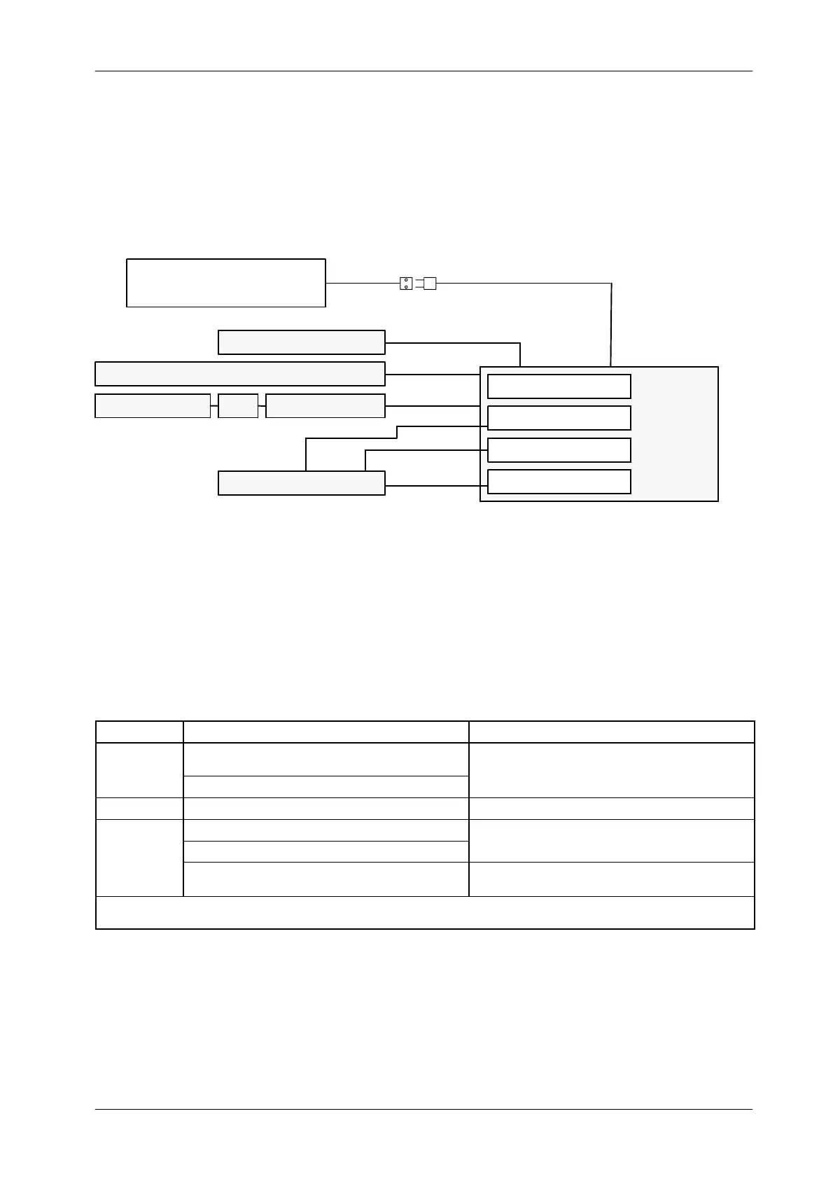
Illustration 3-3
Interconnection Block Diagram for BATTERY POWERED GENERATORS
ROOM ELECTRICAL CABINET
with LINE SAFETY SWITCH
(Customer supplied)
1 1
(Customer supplied)
GENERATOR
CABINET
Serial Comm.
HV Cables
HV TRANSFORMER
POWER MODULE
LF-RAC (LS)
LV-DRAC (HS)
or
X-RAY TUBE
3
3
or
2
or
Serial Comm.
or
SERIAL CONSOLE or TOUCH SCREEN CONSOLE (TPC)
CONTROL CONSOLE
TOUCH SCREEN PC PC INTERFACE BOX
For Serial Generators (RS232 / RS422): Console CPUs are located
inside the Generator Cabinet and Interconnections are factory made.
Only one cable (serial communication) from J5 of the Generator Cabinet
should be connected to the Serial Console, Touch Screen Console or
PC Interface Box.
CABLE RUN FUNCTION REMARKS
1
Single-Phase Line.
110 / 208 / 230 / 240 VAC.
The Unit is connected by a Line Plug.
Power Line
rom a Room Electrical Cabinet with Sa
et
Switch.
Ground.
.
Line plugs and cable are Customer supplied.
2 Control Signals and Ground Cable quantity depends on the options installed (AEC, etc.)
Stator Supply.
Ground.
P
o
ded w
-
a
u
e.
Generator provided with LV-DRAC requires a shielded stator
cable. (Refer to “Installation” document).
Field supplied.
NOTES: -- For wire s ize refer to Section 3.8. Consult to Local Standards for feeder and ground wire size requirements.
-- The system power ground point is located in the Generator Cabinet.
Note .