HF Series Generators
Troubleshooting
TR-1005R4
115
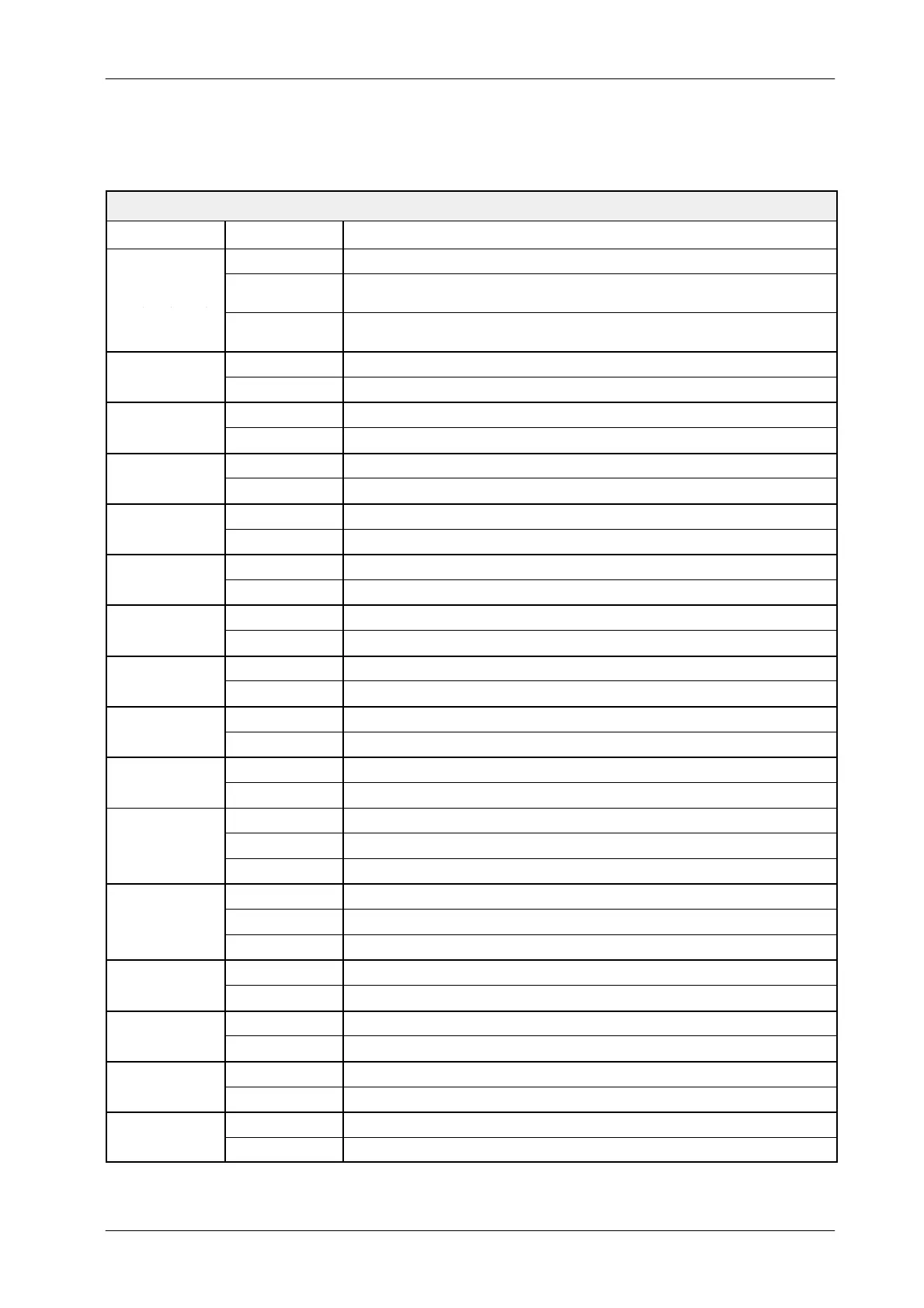
5.9.2 RF ADAPTATION BOARD (A3514--04)
JUMPERS / SWITCHES
JUMPER POSITION DESCRIPTION
Set all jumpers +24 VDC for the inputs PREP ORDER, RAD ORDER, and FLUORO ORDER
JP1, JP3, JP4,
JP8, JP9, JP10,
Remove all
jumpers
230 VAC for the inputs PREP ORDER, RAD ORDER, and FLUORO ORDER
JP12, JP13, JP14
Set only JP1,
JP8 and JP12
115 VAC for the inputs PREP ORDER, RAD ORDER, and FLUORO ORDER
Set Generator +24 VDC for PREP / RAD / FLUORO ORDER
JP2
Removed External supply for PREP / RAD / FLUORO ORDER
A ZOOM 1 output selected from Generator (--9 IN SEL)
JP5
B ZOOM 1 output selected from Table or external control
A ZOOM 2 output selected from Generator (--6 IN SEL)
JP6
B ZOOM 2 output selected from Table or external control
A ZOOM 3 output selected from Generator (--4 IN SEL)
JP7
B ZOOM 3 output selected from Table or external control
A LIH output selected from an external enable signal
JP11
B LIH output selected for Last Image Hold function
A LIH output selected from an external enable signal
JP15
B LIH output selected for Last Image Hold function
A EXP ON/END output active for only RAD exposure
JP16
B EXP ON/END output active for Fluoro and RAD exposure
A For EXP ON output active along the RAD exposure
JP17
B For EXP END output active about 50 ms pulse at the end of the RAD exposure
A For ABC Window adjustment
JP18
B For normal operation
A Pulsed Fluoro sync. from the Line sync.
JP19
B Pulsed Fluoro sync. from the TV Camera video.
C Pulsed Fluoro sync. from an external sync. (TV Camera, digital, etc.)
A For ABC OUT signal from the video in
JP20
B For ABC OUT signal from a negative System ABC signal
C For ABC OUT signal from a positive System ABC signal
A ABC OUT signal generated from a System ABC signal
JP21
B ABC OUT signal incoming directly from the System
Set When JP21 in position A
JP22
Removed When JP21 in position B
Set Normal position
JP23
Removed To reduce noise in the ABC circuitry
A Normal position
JP24
B For Fluoro order enable