Segway®PersonalTransporteri2,x2,x2Turf PartsReplacementGuide 12‐3
BSA Removal and Installation
To remove BSA:
1. MakesureSegwayPTispoweredoffand
unplugged.
2. Establishaservicea
blepowerbase
(page7‐1).
3. Re
movepivotbaseassembly(page9‐14).
4. Re
movechassiscover(page10‐3).
Disconnect(2)balanc
esensorassembly(BSA)
harnessesfromCUboardsocketsbysqueezing
plastictabonconnectorandgentlypulling
connector.
5. Re
movecablesfromBSAcablerouter.
6. Re
moveplasticBSAcablerouter(20532‐
00001).(SeeFigure12‐1foraclose‐upview
.)
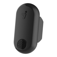
Figure12‐1:BSACableRouter
7. UseT‐106‐lobewrenchtoremove(4)pan‐
head,M3
x0.5x12,self‐tappingscrewsthat
attachbalancesensorassemblytochassis.
DISCARD FASTENERS AFTER REMOVAL! DO NOT
REUSE!
8. Liftbalancesensorassemblyfromchassis.
Avoidtouchingcircuitboardlocatedon
bottomofbalancesensorassembly.
9. Ifyo
uarereusingthisbalancesensor
assembly,placeonappropriateanti‐static
surfaceorESDbag.
Figure12‐2:DisconnectBalanceSensorAssembly
HarnessesfromCUBoards
To install BSA:
1. MakesureSegwayPTispoweredoffand
unplugged.
2. Ta
kenewBSAfromstaticbagandplace
BSAcablerouterontop.Placenewly
assembledBSAinchassis.Routecablesinto
cablerouter.SeeFigure12‐1.
3. Th
read(4)pan‐head,M3x0.5x12,non‐self‐
tappingscrews(20972‐00001)through
balancesensorassemblymountingtabsand
intochassis.SeeFigure12‐2.
For installation, use only Segway approved
fasteners.
4. UsingT‐106‐lobewrench,driveeachscrew
(20972‐00001)andtorqueto1.6N‐m.
5. Insertan
dseat(2)balancesensorassembly
harnessesintoAandBheadersonCU
board.SeeFigure12‐2.
BSA Cable Router
20532-00001
BSAharness
BSA
harness
BSA
19457-00002
 Loading...