- 33 -
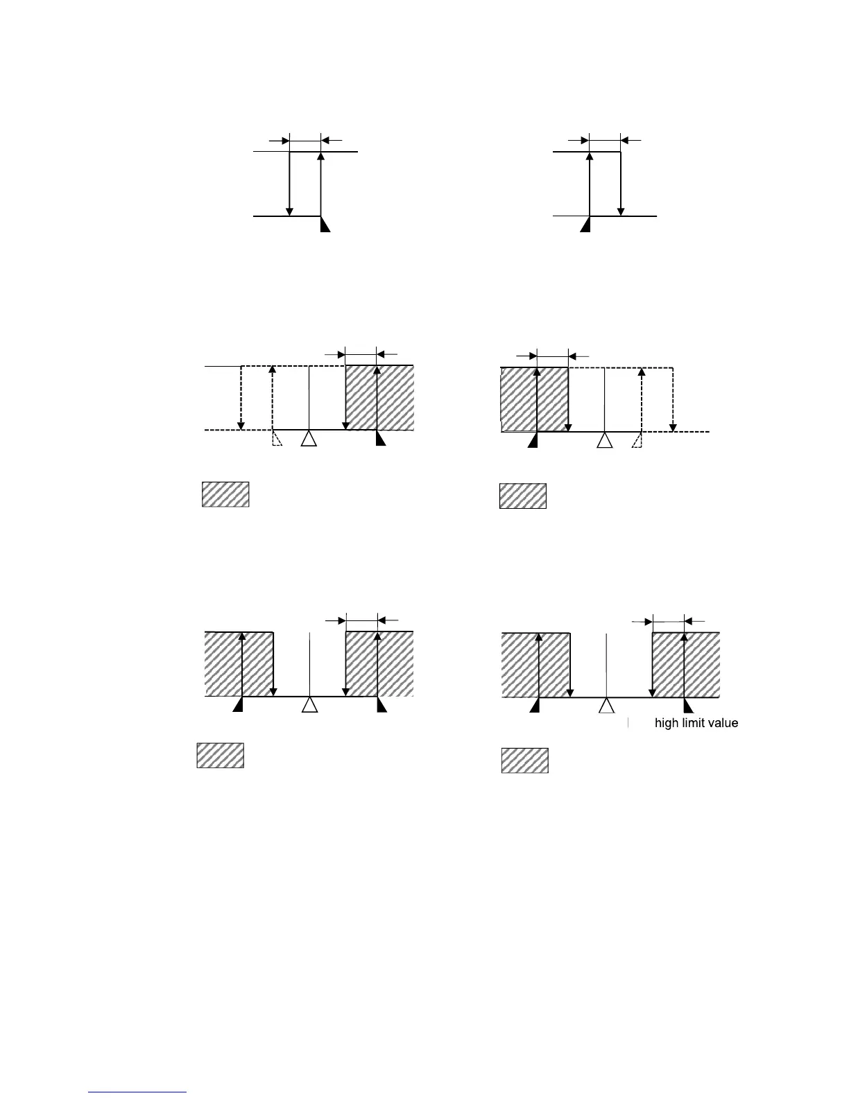
Process high alarm Process low alarm
(Fig. 6-7) (Fig. 6-8)
High limit with standby alarm Low limit with standby alarm
(Fig. 6-9) (Fig. 6-10)
High/Low limits with standby alarm High/Low limits with standby independent alarm
(Fig. 6-11) (Fig. 6-12)
• About Time signal output
Time signal output OFF time and Time signal output ON time are set within total time in one pattern.
After program control starts, Time signal output turns ON during Time signal output ON time after
Time signal output OFF time has elapsed.
During Wait action or program control Hold, progress time of Time signal output stops.
When step time is changed during program control RUN, Time signal output timing is re-calculated
using the changed pattern time.