- 50 -
• Time signal output
Time signal output OFF time and Time signal output ON time are set within one pattern total time.
After program control starts, Time signal output activates during Time signal output ON time after
Time signal output OFF time has elapsed.
During Wait action or program control Hold, progress time of Time signal output stops.
When Step time is changed during program control RUN, Time signal output timing is re-calculated
using the pattern time after change.
Program pattern setting example
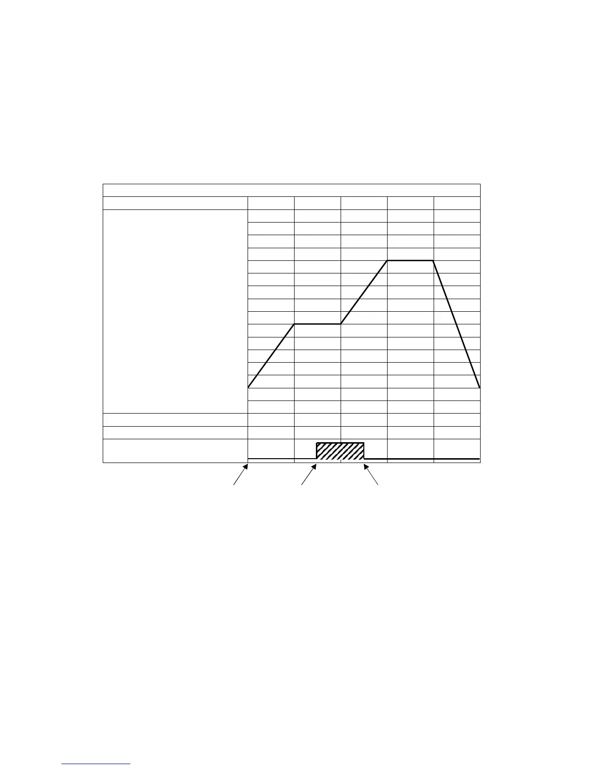
(e.g.) Time signal output setting
Time signal output OFF time: 1 hour
Time signal output ON time: 50 minutes
(Fig. 8.2-13)
Explanation of Time signal output
In the above program pattern example, Time signal output turns ON one hour after program control
RUN starts (30 minutes after the unit entered Step 2). Time signal output turns OFF 50 minutes after
Time signal output turned ON (20 minutes after the unit entered Step 3).
0
500
1000
Program control RUN
ON after 1 hour OFF after 50 minutes