134 FLOWSIC100 Flare · Operating Instructions · 8013344/11L2/V 2-5/2018-10 · © SICK Engineering GmbH
Assembly and Installation
Subject to change without notice
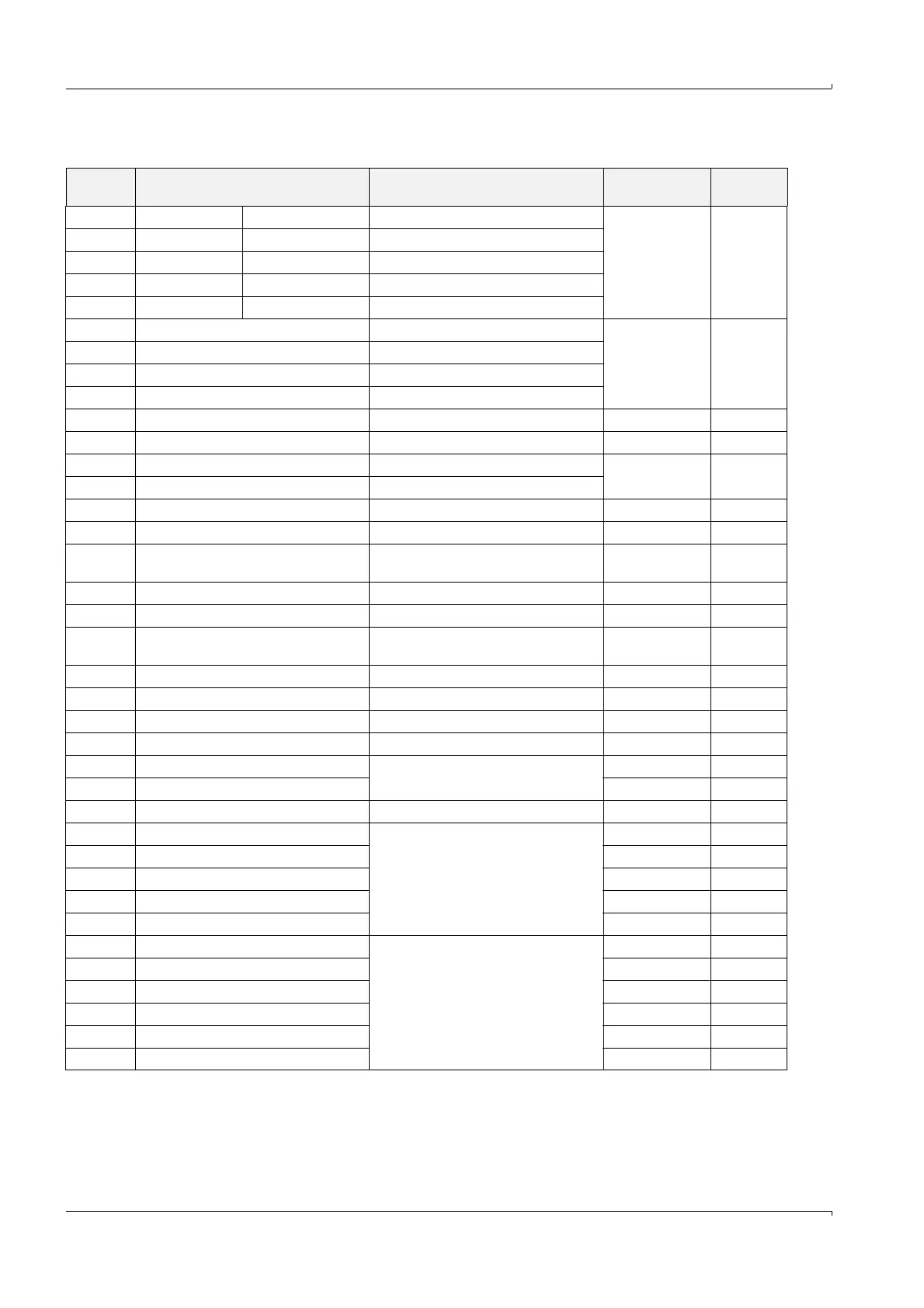
Terminal data
Terminal Marking on the processor board Function Voltage rating
Ampere rat-
ing
1, 2, 3 com, n.c.
1)
, n.o.
2)
relay 1 (malfunc.) Indication of malfunction ≅ 30 V a.c./d.c.
1 A
4, 5, 6 com, n.c.
1)
, n.o.
2)
relay 2 (maint.) Indication of maintenance
7, 8, 9 com, n.c.
1)
, n.o.
2)
relay 3 (check.) Indication of function check
10, 11, 12 com, n.c.
1)
, n.o.
2)
relay 4 (maint.requ.) Indication of maintenance request
13, 14, 15 com, n.c.
1)
, n.o.
2)
relay 5 (limit) Indication of limit violation
16, 18 din1, gnd Digital input 1 (active low forced to gnd)
5.5 V d.c. max. 1 mA
17, 18 din2, gnd Digital input 2 (active low forced to gnd)
19, 21 din3, gnd Digital input 3 (active low forced to gnd)
20, 21 din4, gnd Digital input 4 (active low forced to gnd)
22, 23 +, - Analog output (20 mA) max. 22 V d.c. max. 24 mA
24 gnd Ground
25, 26 ain1, gnd Analog input 1
max. 3 V d.c. 22 mA27, 28 ain2, gnd Analog input 2
29, 30 +, gnd Output 24 V d.c. 22 ... 28 V d.c. 3)
31, 32 +24, -24 Power supply bus sender/receiver unit 1 22 ... 28 V d.c.
33, 34 A, B
RS485 interface bus sender/receiver
unit 1 ± 5 V
max.
100 mA
35 scr. Screen (gnd)
36, 37 +24, -24 Power supply bus sender/receiver unit 2 22 ... 28 V d.c.
38, 39 A, B
RS485 interface bus sender/receiver
unit 2
± 5 V
max.
100 mA
40 scr. Screen (gnd)
41, 42 24 V, gnd Input voltage supply 24V d.c 22 ... 28 V d.c. 3)
43, 44 24 V, gnd Output voltage supply 24V d.c. - 5 V ... +12 V 3)
45, 46 +, - Input 30 V electr. isolated
47, 48 12 V, gnd
Internal voltage (not planned for use)
3)
49, 50 5 V, gnd
51, 52, 53 tx/A, rx/B, gnd RS232/485 3)
54, 56 res 1, gnd
Reserve (not planned for use)
55,56 res 2, gnd
57, 60 res 3, gnd
58, 60 res 4, gnd
59, 60 res5, gnd
71, 73 A, gnd
Interface 1
72, 73 B, gnd
74, 76 +Us, gnd
75, 76 -Us, gnd
77, 79 imp+, res 1
78, 80 imp-, res 2