88 FLOWSIC100 Flare · Operating Instructions · 8013344/11L2/V 2-5/2018-10 · © SICK Engineering GmbH
Assembly and Installation
Subject to change without notice
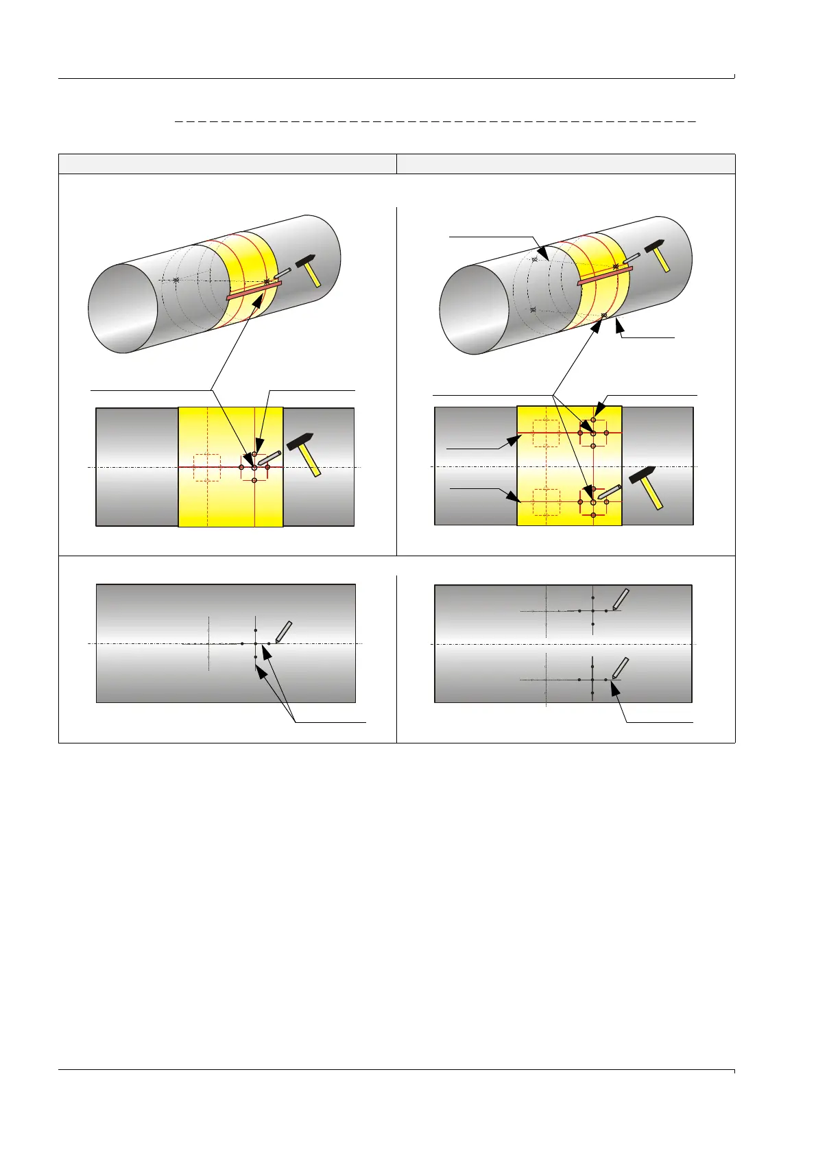
Fig. 37 Marking the nozzle positions on the pipeline
1-path measurement 2-path measurement
7) Roll the strip back around the pipeline and mark the nozzle positions with crossing and marking points by using a metal center punch.
8) Take the strip off again and join the additional markings with a line.
Crossing point (marking for
the center of the nozzle
Marking point
(aid for aligning
the nozzle
Path 1
Path 2
Path 1
Path 2
Crossing point (marking for
the center of the nozzle
Marking point
(aid for aligning
the nozzle