Assembly and Installation
FLOWSIC100 Flare · Operating Instructions · 8013344/11L2/V 2-5/2018-10 · © SICK Engineering GmbH 89
Subject to change without notice
Determining the nozzle position(s) and marking on the pipeline for probe type FLSE100-
EXPR
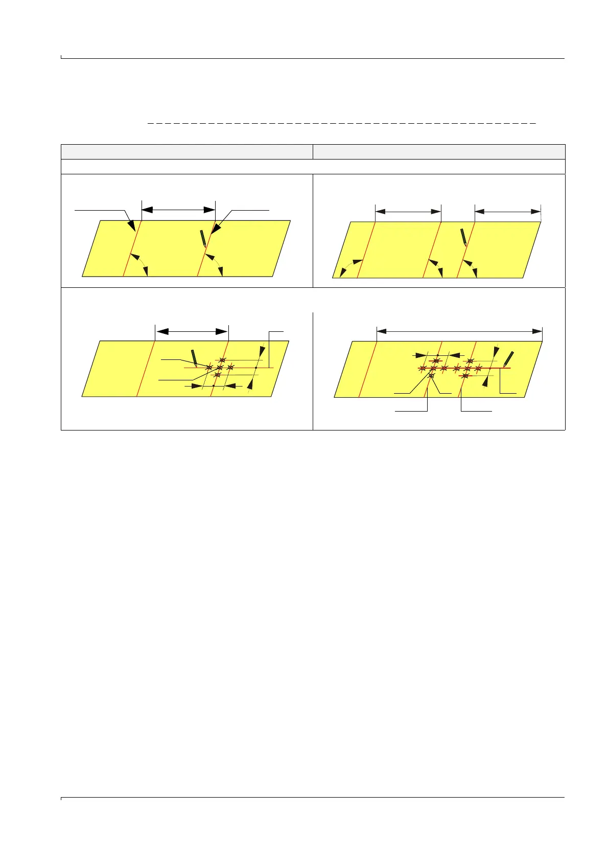
Fig. 38 Determining the nozzle position(s)
1-path measurement 2-path measurement
1) Start preparation work as shown in
→
pg. 86, Fig. 35.
3) Draw a guide line (1) for the nozzle position(s), mark the crossing points (2) and draw marking points (3) in distance 80 mm (x) from
the crossing points.
Overlap line U/2 Kink line
90 ° 90 °
2a) Roll the strip out again and mark the kink line.
90 ° 90 ° 90 °
2b) Roll the strip out again and mark the lines as follows:
2.498•r 2.498•r
r = U/2
x x
U
2 3 1
x
x
Path 1 Path 2