Chapter 9 Operating Instructions
M4000 Adv., Adv. A/P, Area
96 © SICK AG • Industrial Safety Systems • Germany • All rights reserved 8010797/YT72/2016-02-19
Subject to change without notice
Commissioning
In the delivery with the receiver for the M4000 Advanced with integrated laser align-
ment aid you will find two self-adhesive alignment templates (one template for the
deflector mirror and one for the sender). Keep both alignment templates at hand. You
will find further information on the alignment templates as well as a master for copying
in the annex 15.3.
WARNING
Secure the plant/system. No dangerous state possible!
Ensure that the dangerous state of the machine is (and remains) switched off! During the
alignment process, the outputs of the multiple light beam safety device are not allowed to
have any effect on the machine.
How to align the M4000 Advanced with the aid of the integrated alignment aid:
Check with a spirit level whether the devices and the deflector mirrors, if used, are
mounted vertically.
Check whether the following points are the same distance from the floor:
– first beam of the sender
– first beam of the receiver
– when using deflector mirrors: centre of the first mirror surface
Loosen the clamping bolts which hold the multiple light beam safety device in place.
Adhere the alignment template for mirrors to the individual mirror on the mirror pillar
that is used to deflect the beam to be aligned. If you start the alignment with the first
beam as per these instructions, this is the bottom mirror on the mirror pillar
(see Fig. 64).
Activate the laser alignment aid by switching on the power supply to the multiple light
beam safety device.
You can also activate and deactivate the laser alignment aid via the CDS.
Rotate the receiver until the alignment beam is incident in the centre of the hole in the
alignment template (see Fig. 64). If further mirror columns are used, use the alignment
template for all further mirrors on the mirror columns.
If you do not use an alignment template, the alignment beam must be incident approx.
23.5 mm above the centre of the mirror.
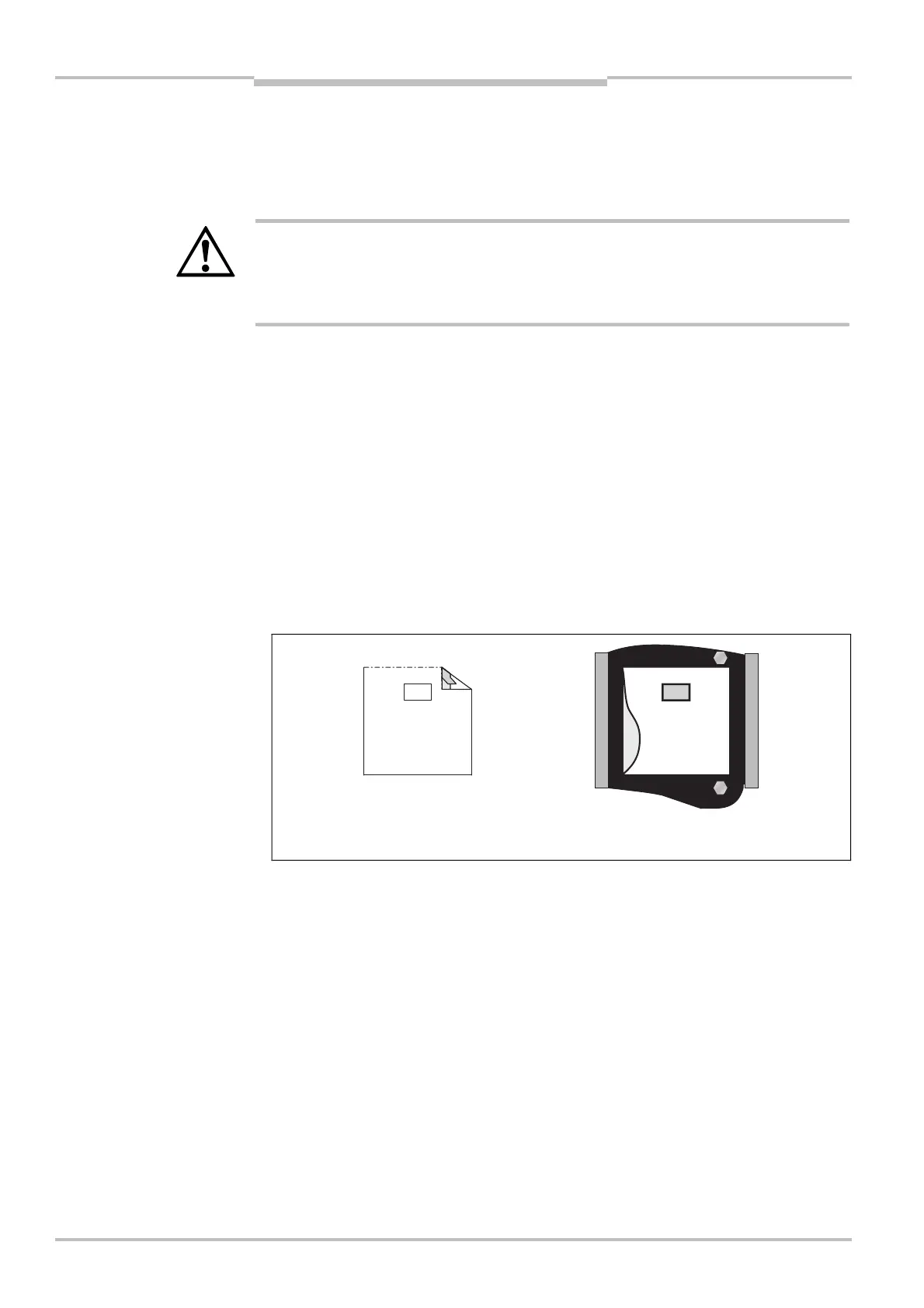
Fig. 63: Attaching the
alignment template for
mirrors
Note
Note
Remove protective film from the
self-adhesive strip on the rear
Adhere alignment template to the
surface of the individual mirror

 Loading...


