Operating Instructions Chapter 9
M4000 Adv., Adv. A/P, Area
8010797/YT72/2016-02-19 © SICK AG • Industrial Safety Systems • Germany • All rights reserved 99
Subject to change without notice
Commissioning
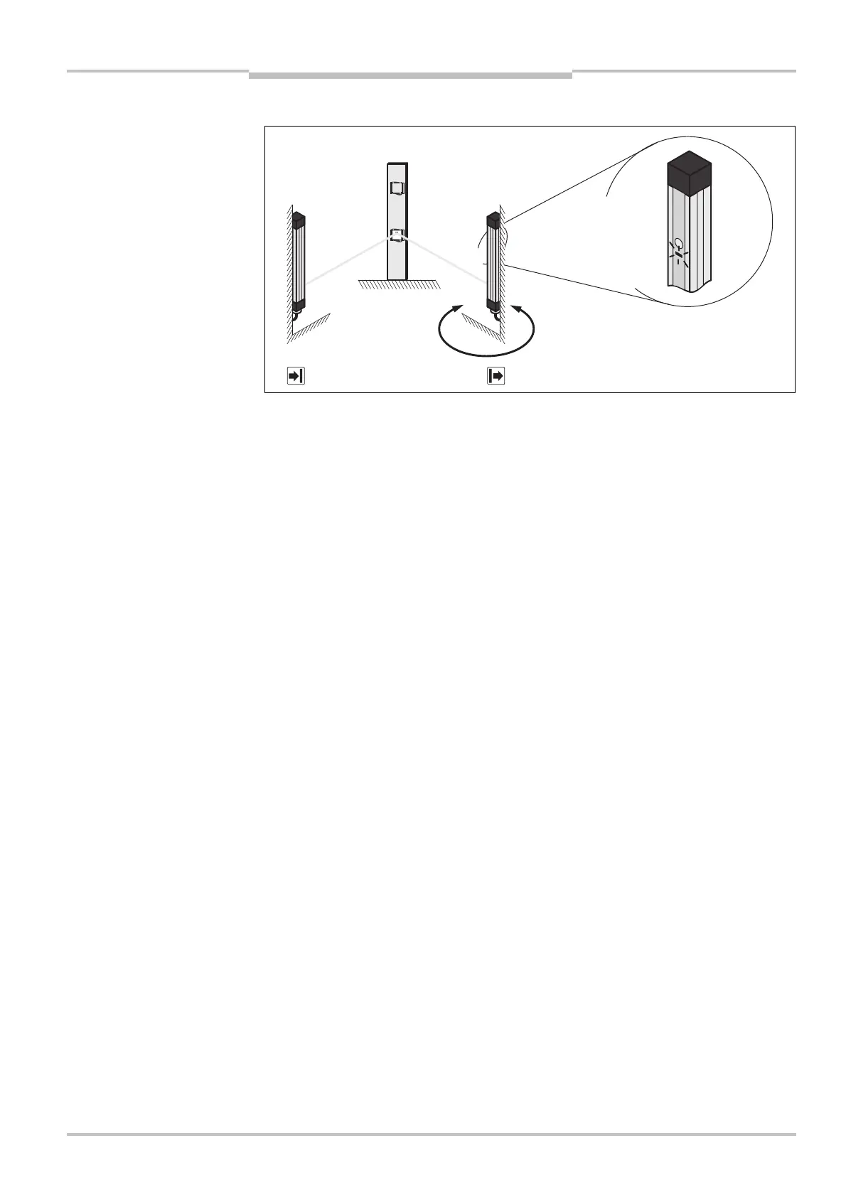
Rotate the sender until the display screen illuminates.
Remove the alignment template. Watch the alignment information on the 7Esegment
display of the receiver (see Tab. 37). The optimal alignment of the beam near the 7Eseg-
ment display is achieved when a appears on the 7Esegment display.
When the alignment information on the 7Esegment display goes out (no indication), then
all other beams are already aligned.
The sender is only aligned once. This step is not necessary when aligning other beams.
Fix the sender in place.
Align the other beams using the steps described.
When aligning the second and all further beams, it may occur that the laser beams for
beams already aligned (e.g. the first beam) are no longer incident to the target on the
alignment template (when this is fitted again). This situation has no effect on the accu-
racy of the overall alignment.
Using the clamping bolts, fix the receiver in place.
Switch the power supply off and then back on again and check via the 7Esegment dis-
play whether the alignment is correct after tightening the clamping bolts (see Tab. 37).
All alignment templates used must be removed after the alignment procedure!
Fig. 68: Alignment of the
sender using the laser
alignment aid
Notes
Note
Note
If the alignment is correct the
display screen illuminates.