3 SYSTEM DESCRIPTION
8020065-ZSP4/2017-08-10|SICK
OPERATING INSTRUCTIONS | Master Data Analyzer
Subject to change without notice
4 – Controller MSC800
The controller housing contains the MSC800 system controller and the power supply unit
for the central voltage supply.
Fig. 9: Controller MSC800
The MSC800 is the system’s central control unit. It controls the coordination of the
individual components and processes all incoming signals. The measurement results are
transmitted via the Ethernet interface to the higher-level customer system.
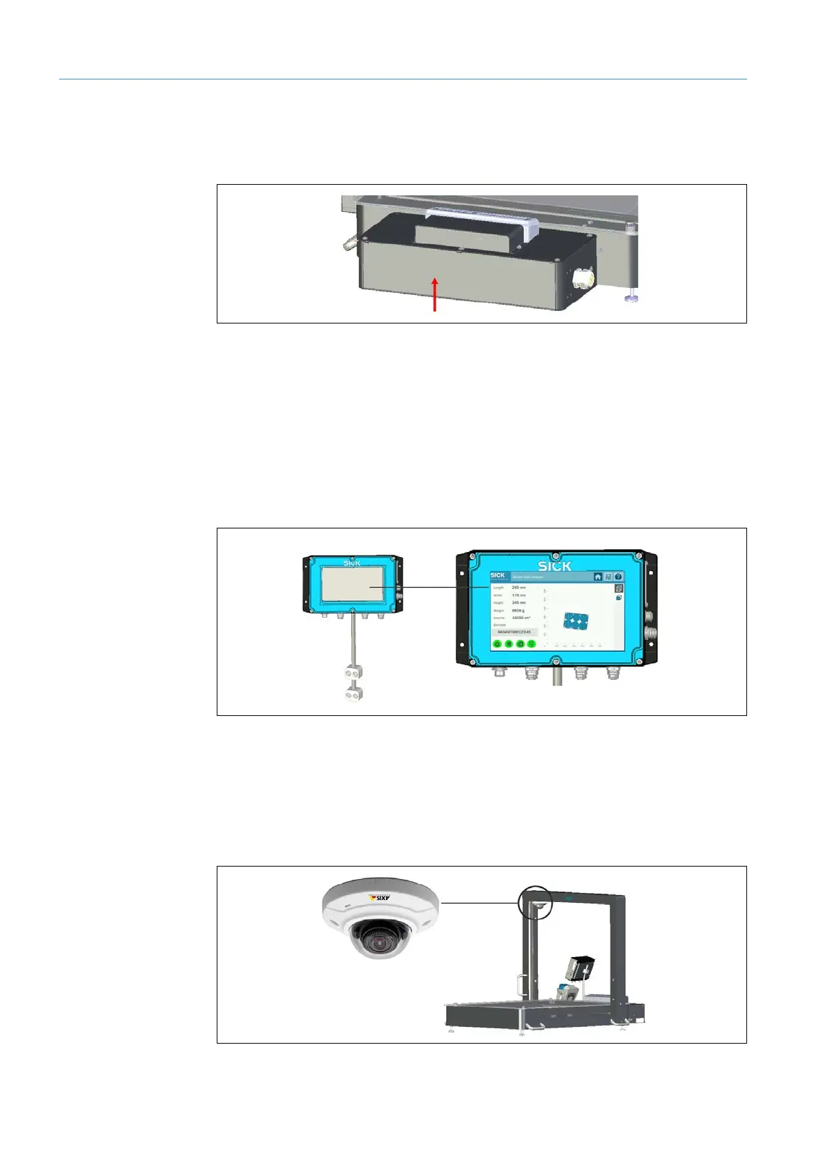
5 – Display
The display is the system’s central visualization unit. It displays the measured values from
the various components during operation and allows for the convenient handling of error
messages.
Fig. 10: Display
6 – IP camera (MDA650 Image/MDA800 Image only)
An IP camera mounted on the measurement gantry generates a photo-realistic image of
the object during the measurement process. The photo is transmitted to the higher-level
customer system together with the measurement data.
The IP camera is supplied with power via PoE (power over Ethernet).
Fig. 11: IP camera (MDA650 Image/MDA800 Image only)