13.6 Dimensional drawings
ø 86
106,6
80,2
50,5
29,731,519
M5 × 7,5
a
b
3
2
1
c
-45°225°
90°
65
44
24
26,3
100,6
102,5
117,5
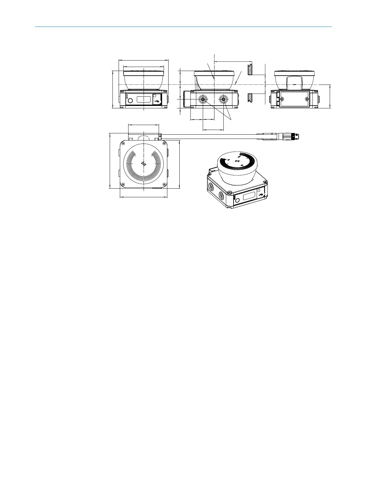
Figure 52: Dimensional drawing
All dimensions in mm.
1
Mirror rotational axis
2
Scan plane
3
Required viewing slit
•
a: L
ength of the viewing slit
•
b: Minimum height above the scan plane
•
c: Minimum height below the scan plane
Required viewing slit
If t
he device is installed in paneling, for example, you must ensure that the laser beam
can exit unhindered. The reflected laser beam must also reach the device unhindered.
That means the viewing slit must be large enough.
The required minimum height and width of the viewing slit depends on the following
parameters, among others:
•
Deviation from the ideal flatness of the scan field at the end of the viewing slit
•
Light spot size at the end of the viewing slit
•
Vibrations that affect the flatness of the scan field or the geometry of the viewing
slit
For a viewing slit with length a ≤200mm, the viewing slit must be at least 28mm high
(b, c ≥14mm). The viewing slit must be wide enough to leave at least 16mm of space
free next to each field.
If the viewing slit is longer (a >200mm), a case-by-case consideration is required.
►
Contact the responsible SICK subsidiary.
13 T
ECHNICAL DATA
142
O P E R A T I N G I N S T R U C T I O N S | nanoScan3 – EtherNet/IP™ 8027909/2023-02-22 | SICK
Subject to change without notice