5.4 Mounting the device
Prerequisites
•
Pr
oject planning has been completed.
•
Mount according to project planning.
•
Installation location provides protection against moisture, dirt and damage.
•
Status indicators are easily visible after mounting.
Approach
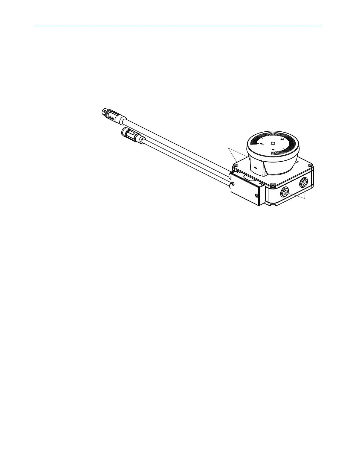
Figure 31: Mounting safety laser scanner
1
Side M5 threaded hole
►
Use all f
our sides of M5 threaded holes for direct mounting, so the values given in
the data sheet for vibration and shock resistance are achieved.
►
Maximum depth of thread engagement: 7.5mm.
►
Tightening torque: 4.5Nm … 5.0Nm.
►
In case of strong vibrations, use screw locking devices to secure the fixing screws.
Complementary information
T
o facilitate mounting and alignment, SICK offers mounting kits as accessories.
Further topics
•
"Pr
oject planning", page 19
•
"Dimensional drawings", page 142
•
"Accessories", page 145
5 MOUN
TING
56
O P E R A T I N G I N S T R U C T I O N S | nanoScan3 – EtherNet/IP™ 8027909/2023-02-22 | SICK
Subject to change without notice