7.12.6 Drawing in points that cannot be monitored
Overview
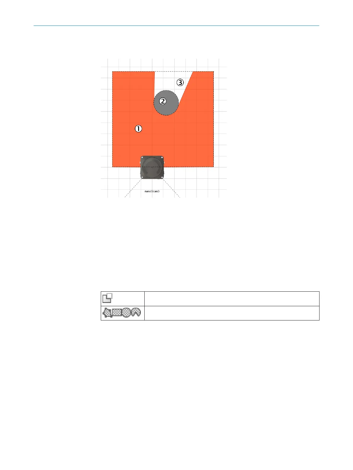
Figure 40: Area that cannot be monitored
1
Protective field
2
Marked column
3
Area that cannot be monitored
The area to be monitored is scanned radially 1. F
or this reason, shadows 3 are
formed by objects in the room 2 (support columns, separator grids, etc.). The safety
laser scanner cannot monitor these areas.
You draw objects that limit the field of view of the safety laser scanner as masked
areas.
Table 20: Mask areas
Mask areas
Hatched drawing tools
Approach
1.
Click on the Mask areas tool.
✓
The tools you can use to draw fields are shown crosshatched.
2. Choose a drawing tool.
3. Draw the masked area.
✓
The masked area is shown in gray.
✓
The field editor shows the shadowing of the masked area.
7.12.7 Enable propose field
Overview
Y
ou can have a protective field or warning field suggested by Safety Designer.
For this purpose, the safety laser scanner scans the visible surrounding contour several
times. Based on the data obtained, the Safety Designer suggests the contour and size
of the field.
7 C
ONFIGURATION
78
O P E R A T I N G I N S T R U C T I O N S | nanoScan3 – EtherNet/IP™ 8027909/2023-02-22 | SICK
Subject to change without notice