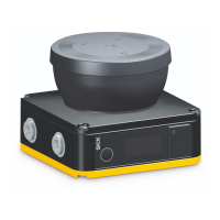
nanoScan3 Pro – EtherNet/IP™
Measurement uncertainty
5)
Typ. ±25mm
1)
In the event of heavy contamination, the safety laser scanner displays a contamination error and
s
witches all safety outputs to the OFF state.
2)
In close proximity (50mm-wide area in front of the optics cover), the detection capability of the safety
laser scanner may be restricted. If required, this area must be secured using an undercut or frame, for
example.
3)
W × H when the laser beam exits at a 90° angle to the front.
4)
This laser product has laser class 1 according to IEC60825-1:2014. In some cases, evaluation is
required according to the older IEC60825-1:2007 standard, e.g. by employers in the EU according to
Directive 2006/25/EC. According to the older IEC60825-1:2007 standard, laser class 1M must be
used as the basis.
5)
Typical values at 20°C and remission factor = 1.8%, distance = protective field range.
The measured values are less accurate for reflectors or reflective surfaces because the distance meas‐
urement is designed for lower remission values.
Complementary information
F
or more technical data specifically relating to the measurement data, see the technical
information “microScan3, outdoorScan3, nanoScan3: Data output via UDP and TCP/IP”
(part number 8022706).
13.3 Response times
Overview
T
he protective device’s response time is the maximum time between the occurrence of
the event leading to the sensor’s response and supply of the switch-off signal to the
protective device’s interface (for example OFF state of the OSSD pair).
In addition to the protective device’s response time, further signal transmission and
processing also influence the time up until the end of the dangerous state. This
includes a control’s processing time and the response times of downstream contactors,
for example.
Response time
T
he safety laser scanner’s response time depends on the set multiple sampling.
You can calculate the response time using the following formula:
t
R
= n × 30ms + 25ms
Where:
•
t
R
=response time
•
n = Multiple sampling setting (default: n = 2)
13.4 Sensing range
Protective field range
T
he effective protective field range depends on the object resolution that has been set.
Table 38: Protective field range
Resolution Protective field range
≥70mm 3.00m
60mm 2.60m
50mm 2.15m
40mm 1.60m
30mm 1.25m
20mm 1.25m
TECHNICAL DATA 13
8027909/2023-02-22 | SICK O P E R A T I N G I N S T R U C T I O N S | nanoScan3 – EtherNet/IP™
121
Subject to change without notice

 Loading...


