3 Product description
3.1 Device overview
Overview
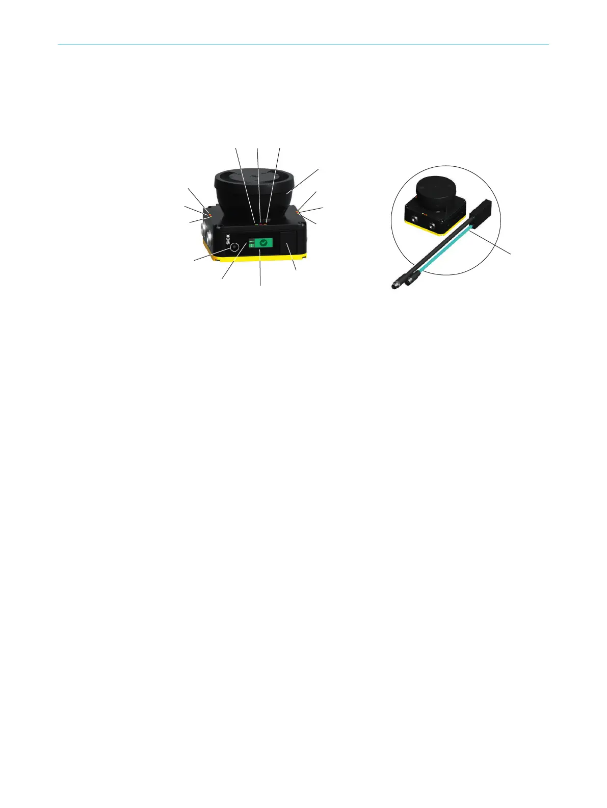
Figure 2: Device overview
1
LED ON status
2
LED OFF status
3
LED restart interlock/warning field
4
Optics cover
5
USB connection
6
Display
7
Network LEDs
8
Pushbutton
9
System plug
Complementary information
Position and direction information in this document:
•
The top is the side of the device on which the optics cover is located.
•
The bottom is the side of the device opposite the optics cover.
•
The front is the side of the device on which the display is located. The 90° angle of
the sector of a circle scanned by the device points in this direction.
•
The back is the side of the device opposite the display. The sector of a circle not
scanned by the device lies in this direction.
Further topics
•
"C
onnecting", page 57
•
"Status indicators", page 97
3.2 Structure and function
The safety laser scanner is an electro-sensitive protective device (ESPE) which scans its
sur
roundings two-dimensionally using infrared laser beams.
The safety laser scanner forms a protective field using the invisible laser beams. This
protective field protects the hazardous area and enables hazardous point protection,
access protection or hazardous area protection. As soon as an object is situated in the
protective field, the safety laser scanner signals the detection by means of a signal
change at the safety output. The machine or its control must safely analyze the signals
(for example using a safe control or safety relays) and stop the dangerous state.
PRODUCT DESCRIPTION 3
8027909/2023-02-22 | SICK O P E R A T I N G I N S T R U C T I O N S | nanoScan3 – EtherNet/IP™
13
Subject to change without notice