Basics of Path Interpolation
2.2 Coordinate system
TO Path Interpolation
Function Manual, 11/2010
17
2.2 Coordinate system
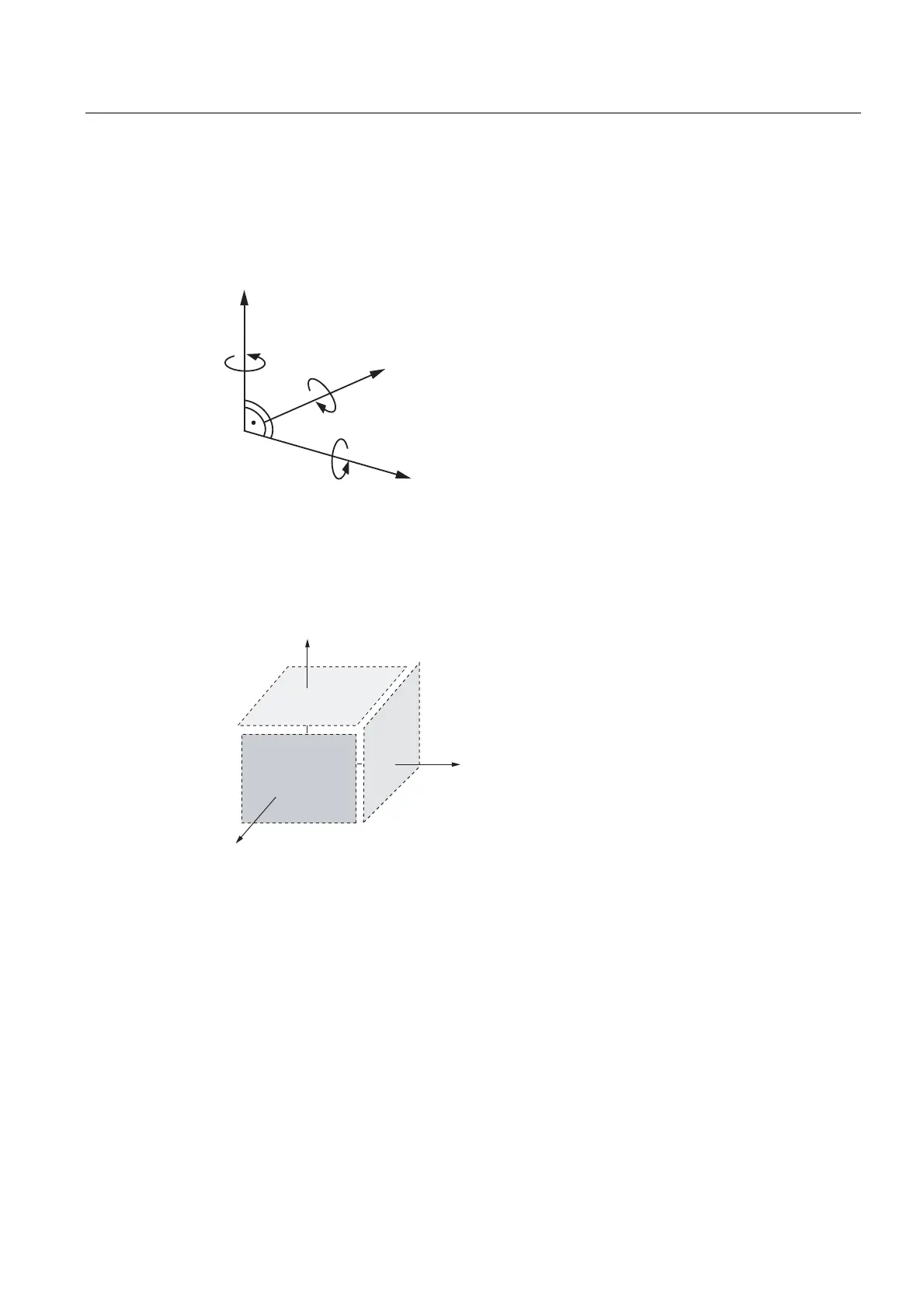
The path interpolation functions require a Cartesian coordinate system. A clockwise,
rectangular coordinate system in accordance with DIN 66217 is used.
The user programs in this right-handed system, irrespective of the real kinematics.
z
y
x
Figure 2-5 Cartesian coordinate system, right-handed system
Main planes
It is easy to program two-dimensional motions (2D) directly in one of the three main planes
X-Y, Y-Z, or Z-X. In this case, the third coordinate remains constant and does not have to be
programmed.
[
\
]
<B=
=B;
;B<
Figure 2-6 Main planes in 3D
2.3 Modulo properties
Both path axes and positioning axes can be used as modulo axes. However, no modulo
range change for the path axis may occur in the path traversal area. The kinematic
transformation does not take account of any modulo range change.
Consequently, only one modulo range of the path axis can be used for the traversal area on
the path object. The activation of the path interpolation defines the modulo range for the path
motion.

 Loading...


