Basics of Path Interpolation
2.13 Kinematic adaptation
TO Path Interpolation
Function Manual, 11/2010
47
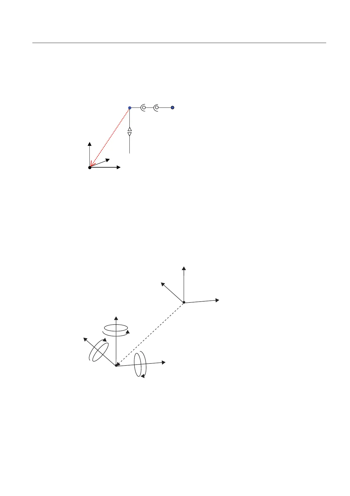
2.13.2.8 Offset of the kinematic zero point relative to the Cartesian zero point
An offset of the kinematic zero point of the transformation relative to the Cartesian zero point
can be set in the basicOffset configuration data.
A
1
A
2
basicOffset
A
3
x+
z+
y+
.LQHPDWLF]HURSRLQW
&DUWHVLDQ]HURSRLQW
(QGSRLQW
Figure 2-30 Example of kinematic offset
The above example produces negative values for the kinematic offsets.
Offset in example:
x: -100
y: -100
z: -200
With SIMOTION V4.2 and higher, not only can the BCS be offset but also rotated, allowing
for any rotation of the coordinate system from the kinematics zero point. This allows flexible
assignment of the BCS to the handling equipment's kinematics.
\
]
[
\DZ
UROO
%&6
SLWFK
\
]
[
.LQHPDWLFV]HURSRLQW
Figure 2-31 Coordinate system offset and rotation
The rotations are undertaken after the offset in the following order:
1. Roll around x axis
2. Pitch around (already rotated) y axis
3. Yaw around (already twice rotated) z axis

 Loading...


