Basics of Path Interpolation
2.13 Kinematic adaptation
TO Path Interpolation
48 Function Manual, 11/2010
A
1
A
2
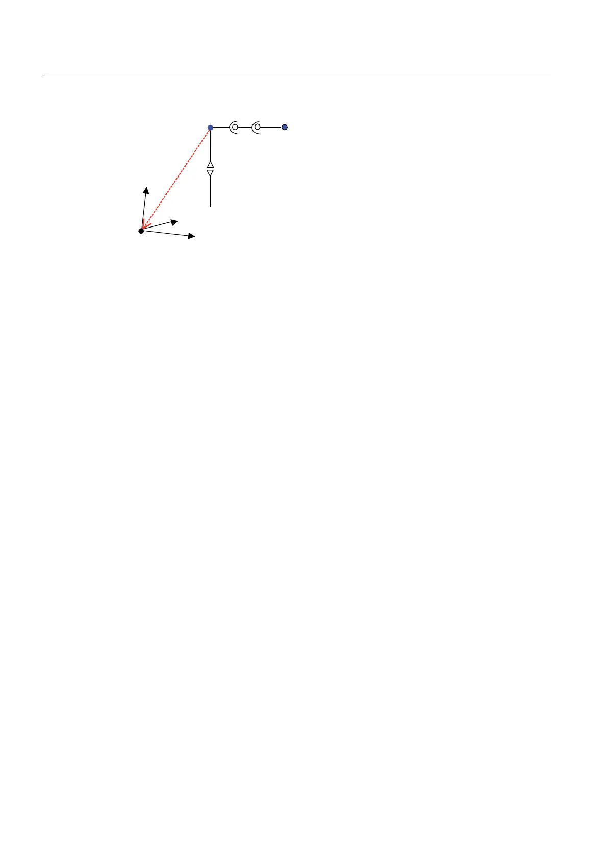
basicOffset
A
3
x+
z+
y+
&DUWHVLDQ]HURSRLQW
(QGSRLQW
.LQHPDWLFV]HURSRLQW
Figure 2-32 Example of kinematics offset with rotation
Offset and rotation (around the y axis) in the example:
x: -100
y: -100
z: -200
roll: 0°
pitch: +15°
jaw: 0°
2.13.3 Supported kinematics
2.13.3.1 Supported kinematics and their assignment
The following kinematics can be set using the typeOfKinematics configuration data:
● Cartesian 2D/3D gantries (Page 51) (CARTESIAN):
● P
icker ki
nematics:
– Roller picker (Page 52) (ROLL_PICKER)
– Delta 2D picker (Page 54
) (DELTA_
2D_PICKER)
– Delta 3D picker (Pag
e 55) (DELTA_
3D_PICKER)
● SCARA kinem
atics (Page 58) (SCARA)
● Articulated arm kinematics (Page 61) (ARTICULATED_ARM)
● 2-axis articulated arm kinematics (Page 64) (ARTICULATED_ARM
_2D) availabl
e from
V4.2.
● Swivel arm kinematics (Page 65) (SWIVEL_
ARM) available fro
m V4.2.
● Other special kinematics (Page 68).(S
PECIFIC)
A transformation can be se
lected for each path object.
Thus, multiple transformations can be configured/active in a SIMOTION system when
multiple path objects are used.

 Loading...


