Basics of Path Interpolation
2.5 Path interpolation types
TO Path Interpolation
26 Function Manual, 11/2010
retval := _movepathcircular(
pathObject := pathIpo,
pathPlane := X_Y_Z,
circularType := OVER_POSITION_TO_ENDPOSITION,
pathMode := RELATIVE,
x:=10.0, y:=0.0, z:=0.0,
ijkMode := RELATIVE,
i:=5.0, j:=5.0, k:=5.0
);
2.5.5 Polynomial paths
2.5.5.1 Polynomial paths
A polynomial segment enables you to achieve a constant-velocity and constant-acceleration
transition between two geometry elements and to make use of user-programmable curve
shapes, e.g. from a higher-level CAD system.
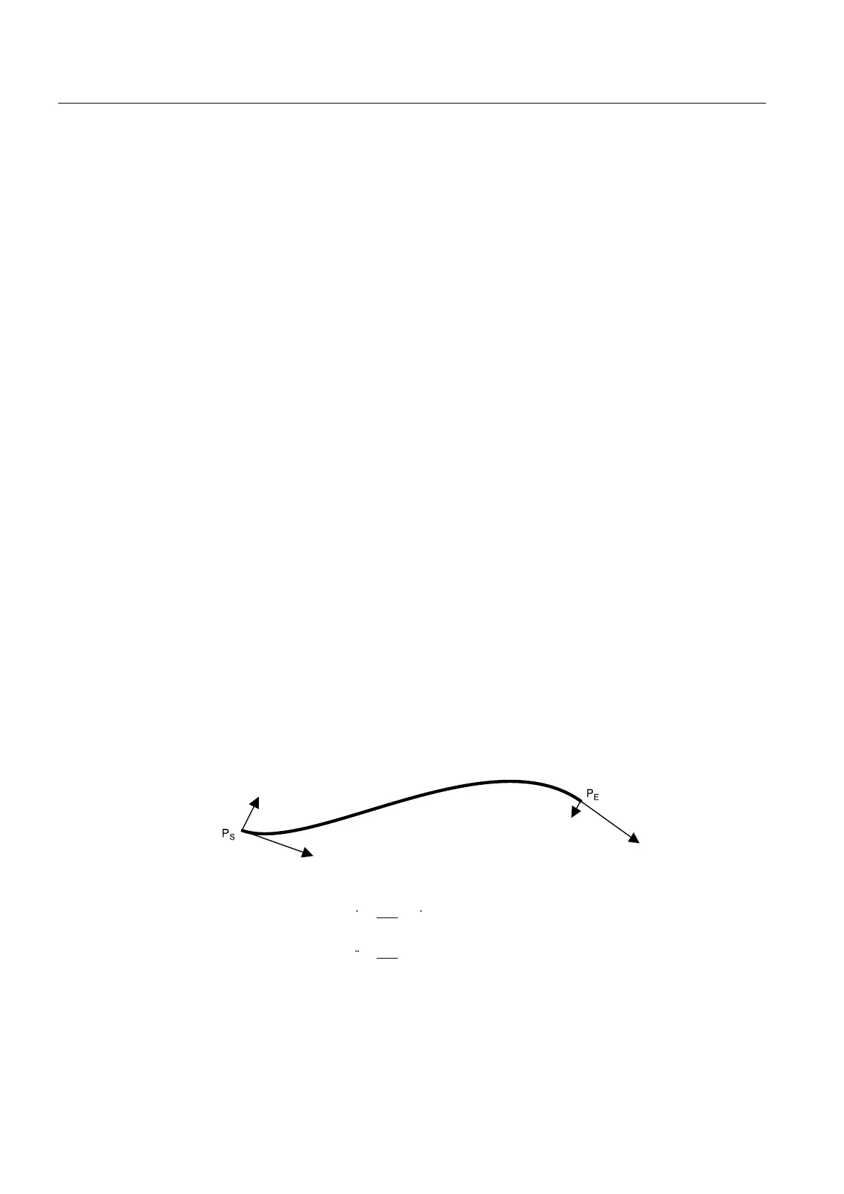
In addition to the implicit start point (P
S
) of the polynomial, the end point (P
E
) as well as four
three-dimensional vectors for defining the polynomial coefficients are specified in the
command parameters of the _movePathPolynomial() command
The vectors are entered in the command using their components. Thus, for example, vector1
is entered with command parameters vector1x, vector1y, and vector1z.
The polynomial can be defined in three ways:
● Direct specification of the polynomial coefficients (Page 28)
● Explicit specification of starting point data (Page 28)
● Attach continuously (Page 30)
For the two explicit spe
cification of the start point data and attach con
tinuously types, the
derivatives at the start and end points of the polynomial are required. They can be
determined using integrated functions.
YHFWRU
YHFWRU
YHFWRU
YHFWRU
3 _3_
d3
ds
3
d 3
ds
2
2
)LUVWJHRPHWULFGHULYDWLYH
WDQJHQWLDOYHFWRU
6HFRQGJHRPHWULFGHULYDWLYH
YHFWRURIFXUYDWXUH
(QGSRLQW
6WDUWLQJSRLQW
9HFWRURIFXUYDWXUH
9HFWRURIFXUYDWXUH
7DQJHQWLDOYHFWRU
7DQJHQWLDOYHFWRU
Figure 2-15 Polynomial description by specification of the geometric derivatives

 Loading...


