Basics of Path Interpolation
2.9 Display and monitoring options on the axis
TO Path Interpolation
38 Function Manual, 11/2010
Note that with active dynamic adaptation, the dynamic axis response is set to the smaller
value from axis acceleration and axis deceleration. Therefore, when an axis has a maximum
acceleration of 1000 mm/s
2
and a maximum deceleration of 500 mm/s
2
, the value for the
deceleration is used for the calculation.
2.8.4 Blending without dynamic adaptation
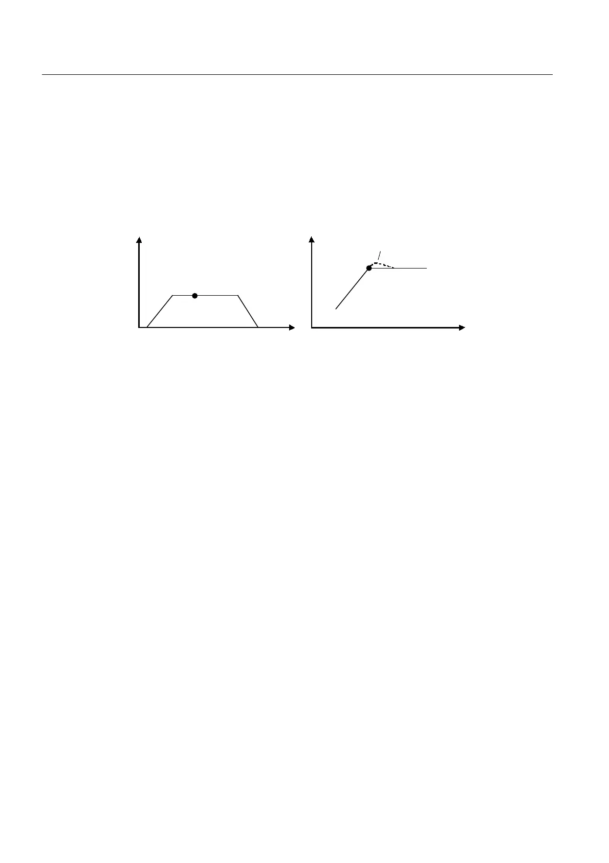
A C B
A
B C
3DWKYHORFLW\
$[LVVSHFLILFVHWSRLQWGHYLDWLRQDVD
UHVXOWRIG\QDPLFUHVSRQVHOLPLWLQJ
&RRUGLQDWH
7LPH
&RRUGLQDWH
Figure 2-26 Example of blending without dynamic adaptation: Straight line - straight line
With this setting, the dynamic limits of the axis are not taken into account in path blending.
The path velocity is controlled as a scalar variable that is independent of direction and
curvature.
A non-tangential attachment of path segments has no effect on the path velocity profile; for
this reason, the velocity is not reduced during blending.
Because the setpoints that are generated for the individual axes are limited to the axis-
specific dynamic limits for the axes, this can result in an axis setpoint error relative to the
setpoint from the path interpolation. This ultimately leads to an axis-specific deviation from
the path in the blending range.
For example, this mode is applicable if the dynamic limits of the axes are to be adhered to on
the path (when approaching positions, for example) but an axis-specific axis setpoint error
relative to the path is acceptable at the segment transitions in the blending range.
2.9 Display and monitoring options on the axis
Display and monitoring options for path motion on the axis
An active path motion is indicated on the path axis in system variable pathMotion.state.
Display of path-synchronous motion on the positioning axis
An active synchronous axis motion is indicated on the positioning axis in system variable
pathSyncMotion.state.
Monitoring for setpoint error
The path axis or positioning axis can be monitored for setpoint errors (discrepancy between
the setpoint specified by the path object and the setpoint output on the axis).
The difference between the setpoint and the actual value is not monitored.

 Loading...


