Basics of Path Interpolation
2.13 Kinematic adaptation
TO Path Interpolation
54 Function Manual, 11/2010
Specification of the radius of the disks on the motors in:
radius1 Disk radius for path axis 1
radius2 Disk radius for path axis 2
Possible link constellations
LinkConstellation Irrelevant (always 1)
2.13.3.5 Delta 2D picker
G1 G2
G3 G4
x+
y+
OHQJWK
OHQJWK
OHQJWK
OHQJWK
RIIVHW$ RIIVHW$
GLVWDQFH'
GLVWDQFH'
=HURSRVLWLRQDQGSRVLWLYH
GLUHFWLRQRIURWDWLRQRIWKH
SDWKD[HV
$D[LV
$D[LV
.LQHPDWLFHQGSRLQW(3
&DUWHVLDQ]HURSRLQW
.LQHPDWLF]HURSRLQW=3
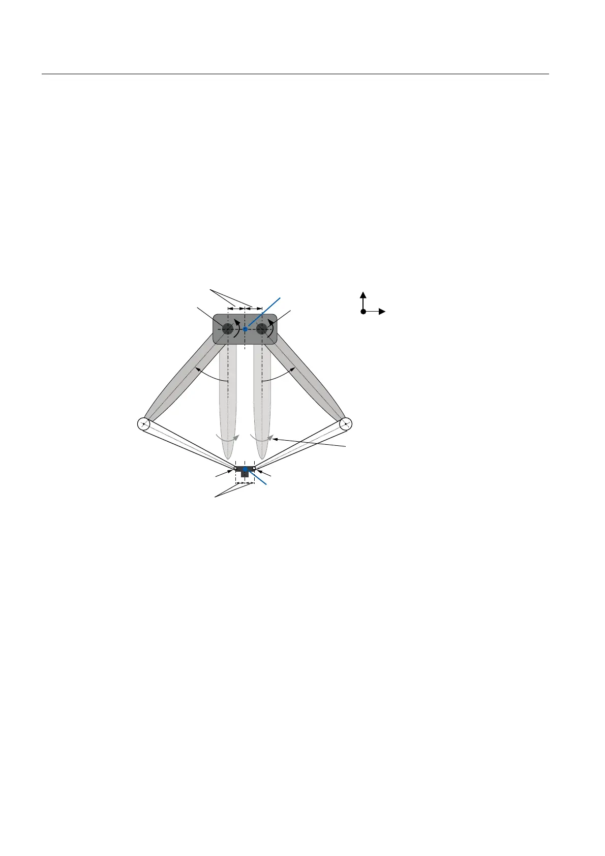
Figure 2-40 Kinematics of Delta 2D picker (X-Y plane example)
Definitions
● The complete structure is contained in one of the two-dimensional main planes. The X-Y
plane is used as an example in the following description.
● A
1
and A
2
designate the two active drive axes of the kinematic structure. They lie on the
straight line y = 0 and are separated from each other by the distance 2x distanceD1.
Their zero position within the kinematic structure corresponds to the orientation of the
upper arm segments (length1) in the direction of the negative Y axis. Positive
displacements occur as shown in the figure.
● It is assumed that always a horizontal orientation of the lower connection plate between
G
3
and G
4
occurs.
This produces y
G3
= y
G4
and a horizontal separation of 2x distanceD2.
● When x
ZP
= y
ZP
= 0, the zero position of the kinematics lies in the center between drive
axes A
1
and A
2
.
● The end point of the direct transformation is defined with its coordinates x
EP
and y
EP
in the
center between G
3
and G
4
. This yields the position for G
3
= (x
EP
-distanceD2; y
EP
) as well
as G
4
= (x
EP
+distanceD2; y
EP
).

 Loading...


