Basics of Path Interpolation
2.13 Kinematic adaptation
TO Path Interpolation
Function Manual, 11/2010
53
x
II
+
y
II
+
(R
1II
,φ
1II
(R
2II
, φ
2II
)
*XLGHUROOHU
$
$
7RRO
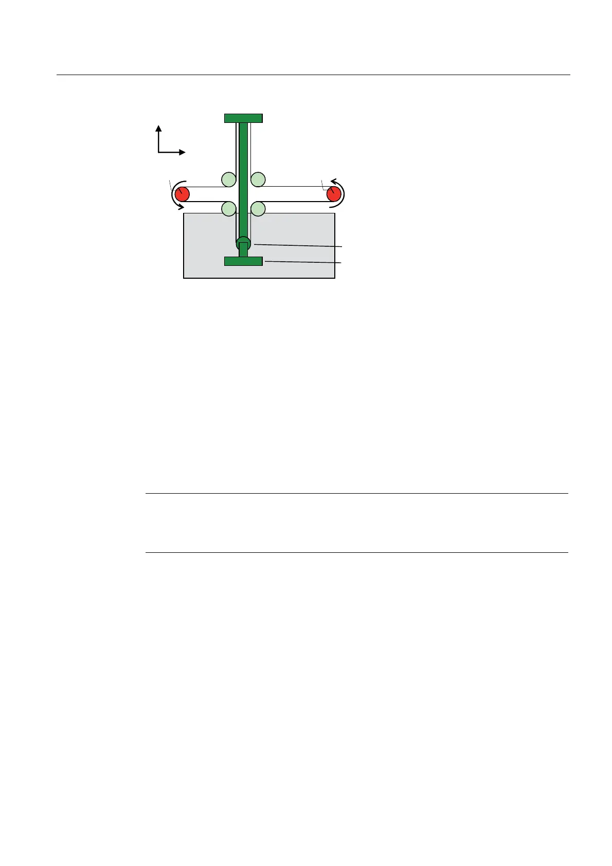
Figure 2-39 Kinematics of roller picker (deflection roll on the tool; this case is not examined here)
The alternative variant with the deflection role on the tool can be derived by converting the
coordinates:
Deflection role on the tool Deflection role on the opposite side of the tool
x
II
* -x
I
y
II
* -y
I
φ
1II
* φ
2I
φ
2II
* φ
1I
R
1II
* R
2I
R
2II
* R
1I
Note
The two path axes must be configured so that 360 axis-units (i.e. mm, degree, etc.) produce
a disk revolution. The "modulo axis" setting should be prevented. See Units (Page 18) and
Modulo properties (Page 17).
Configuration data for roller picker kinematics
typeOfKinematics: ROLL_PICKER Roller picker kinematics type
basicOffset.x Offset of the kinematic zero point relative to the
Cartesian zero point, x-coordinate
basicOffset.y Offset of the kinematic zero point relative to the
Cartesian zero point, y-coordinate
Axis 3 is not available for the roller picker.
config2D Main plane of the path axes

 Loading...


