Basics of Path Interpolation
2.6 Path dynamics
TO Path Interpolation
Function Manual, 11/2010
31
pathObject:=pathIPO,
pathPlane:=X_Y,
pathMode:=ABSOLUTE,
xStart:=30.0,
yStart:=15.0,
xEnd:=50.0,
yEnd:=5.0,
pathPointType:=START_POINT
);
myRetDINT :=
_movePathPolynomial(
pathObject:=pathIPO,
pathPlane:=X_Y,
pathMode:=ABSOLUTE,
polynomialMode:=ATTACHED_STEADILY,
x:=30.0,
y:=15.0,
vector1x:=EndPoly.firstGeometricDerivative.x,
vector1y:=EndPoly.firstGeometricDerivative.y,
vector2x:=EndPoly.secondGeometricDerivative.x,
vector2y:=EndPoly.secondGeometricDerivative.y
);
2.6 Path dynamics
2.6.1 Path dynamics
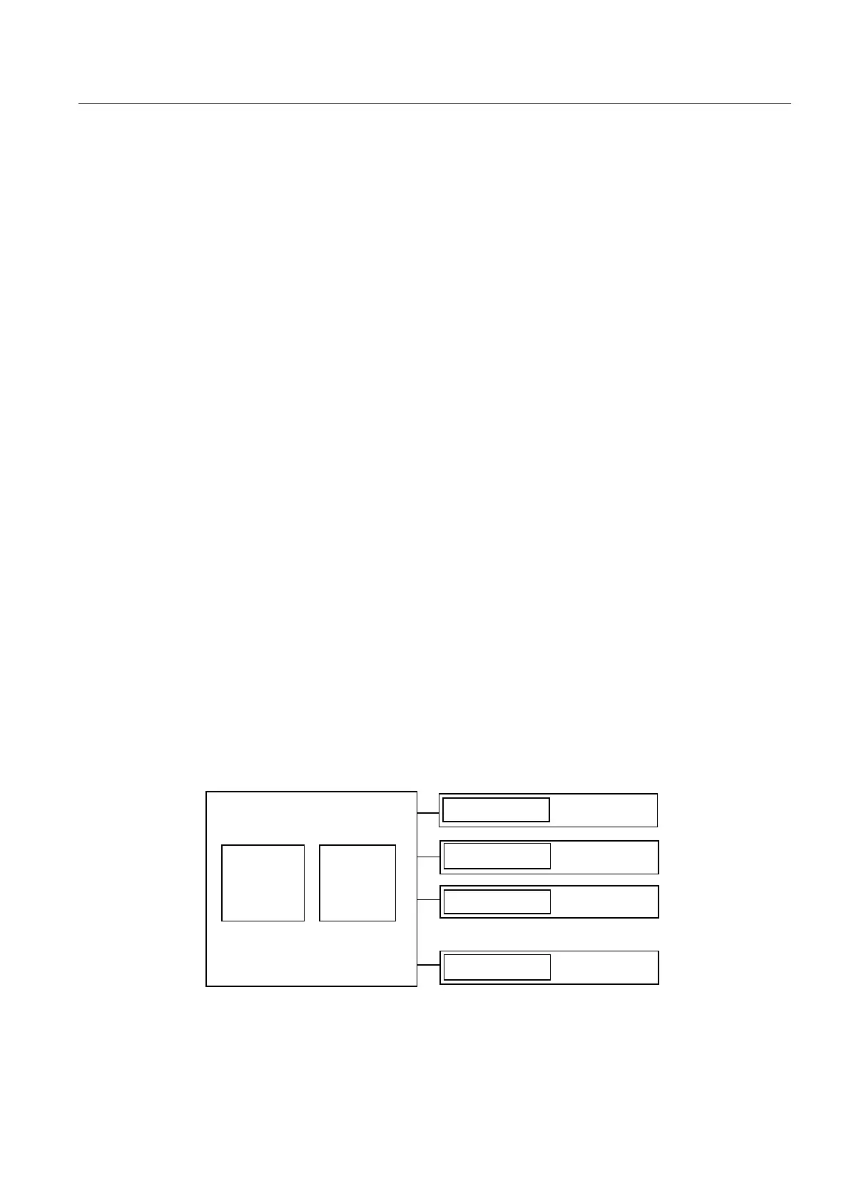
The path dynamics can be specified through preset dynamic values or a dynamic response
profile.
The dynamic limits of the individual axes for motion along the path can also be taken into
consideration.
An error message is output if the dynamic values are exceeded.
3DWKLQWHUSROD
WRUG\QDPLF
SDWKUHVSRQVH
7UDQVIRUPD
WLRQ
3DWKD[LV
3DWKREMHFW
3DWKD[LV
3DWKD[LV
3RVLWLRQLQJD[LV
/LPLWDWLRQWRPD[LPXP
G\QDPLFD[LVUHVSRQVH
/LPLWDWLRQWRPD[LPXP
G\QDPLFD[LVUHVSRQVH
/LPLWDWLRQWRPD[LPXP
G\QDPLFD[LVUHVSRQVH
/LPLWDWLRQWRPD[LPXP
G\QDPLFD[LVUHVSRQVH
Figure 2-21 Path dynamics during path interpolation and dynamic limiting on the axis

 Loading...


