TO Path Interpolation
Function Manual, 11/2010
97
Sample Project for the Path Interpolation
4
4.1 Overview of the example
To illustrate how the path interpolation is configured, the following sections describe a
sample project step-by-step.
The following descriptions assume that the project with the SIMOTION device and the drives
have already been created in the HW Config.
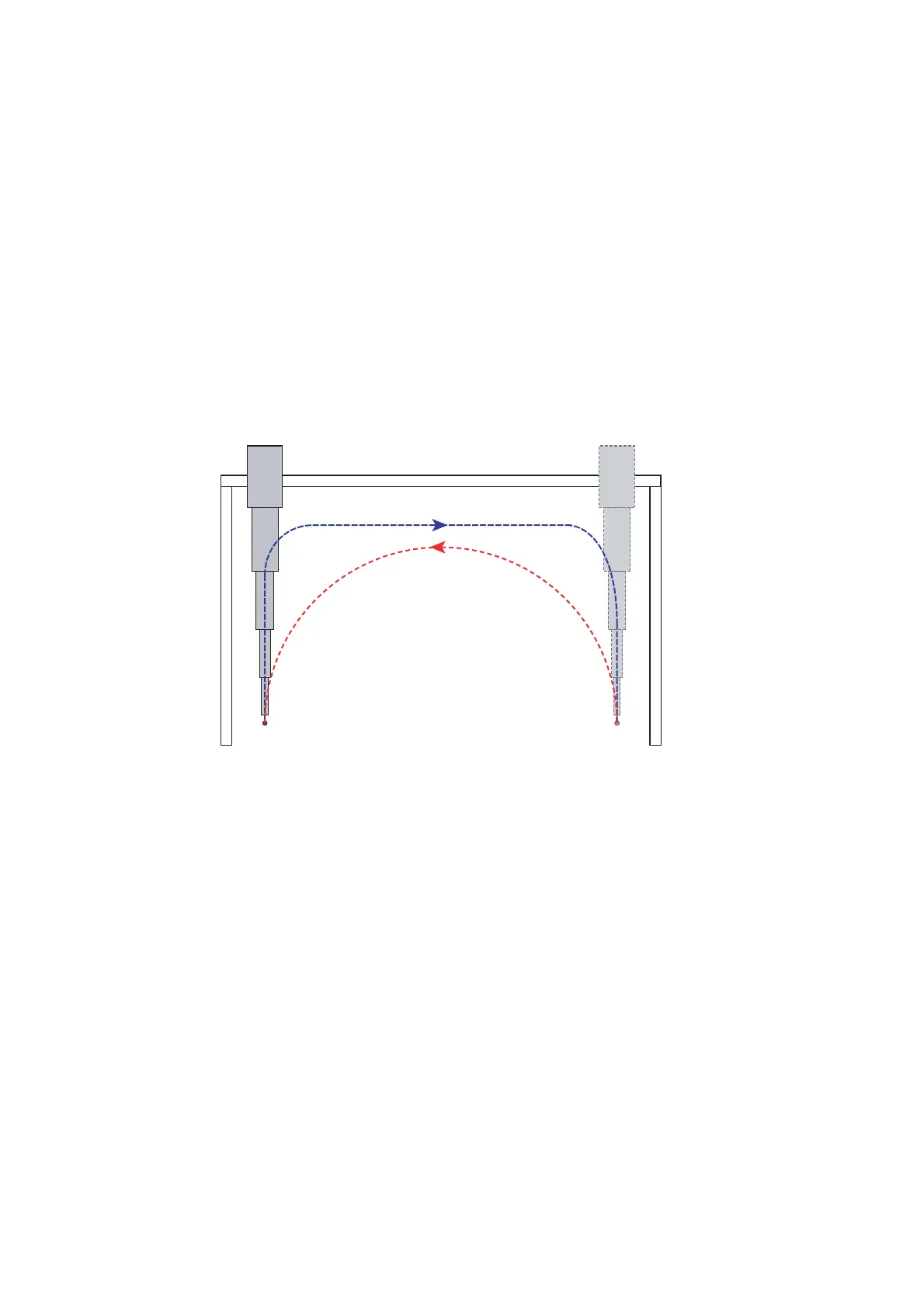
In this example, the following 2D gantry is created:
Figure 4-1 Overview
This 2D gantry comprises the following axes:
● Vertical axis: 1400 cm traversing length, axis zero point at the lowest position
● Horizontal axis: 2000 cm traversing length, axis zero point at the left-hand side
This means the zero point of the path object is at the lower left.
How to create and use the 2D gantry:
● Selecting a technology package
● Creating axes
● Create path object
● Defining the kinematics
● Interconnecting a path object
● Programming a path in MCC
● Checking a motion with trace
To show how a synchronous axis operates, a grabber will also be created at the end of the
example.

 Loading...


