Motor identication:
• [1]: Recommended setting. Measure the motor data at standstill and with the motor rotating.
The converter switches o the motor after the motor data identication has been completed.
• [2]: Measure the motor data at standstill. The converter switches o the motor after the
motor data identication has been completed.
Recommended setting for the following cases:
– You have selected "Speed control" as control mode, however the motor cannot freely
rotate, e.g. for mechanically limited traversing sections.
– You have set "U/f control" as control mode.
• [3]: Measure the motor data while the motor is rotating. The converter switches o the motor
after the motor data identication has been completed.
• [11]: The same setting as [1]. The motor accelerates to the currently set setpoint after the
motor data identication.
• [12]: The same setting as [2]. The motor accelerates to the currently set setpoint after the
motor data identication.
Calculating the motor parameters: Select "Complete calculation".
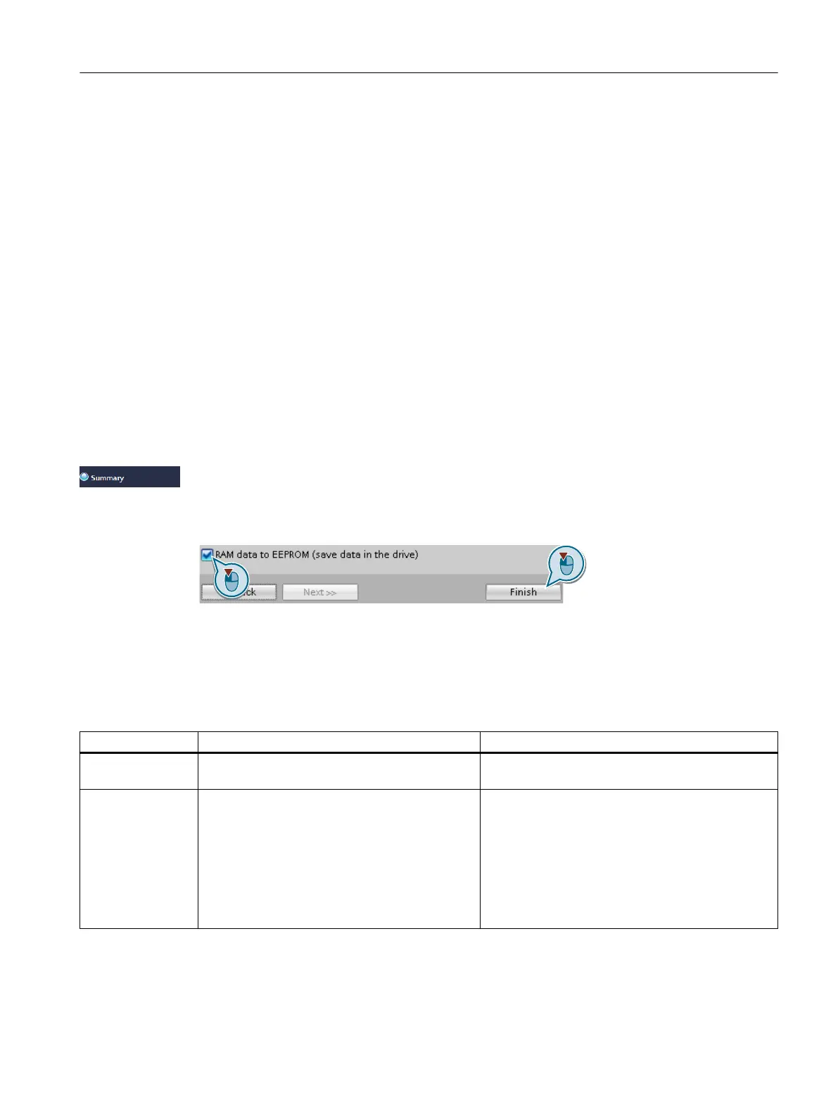
Set the check mark for "RAM data to EEPROM (save data in the drive)" to save your data in the
converter so that it is not lost if the power fails.
Select "Finish".
You have entered all of the data that is necessary for the quick commissioning of the
converter.
❒
Select a suitable control mode
Control mode U/f control or ux current control (FCC) Encoderless vector control
Motors that can
be operated
Induction motors Induction and synchronous motors
Application exam‐
ples
• Pumps, fans, and compressors with ow char‐
acteristic
• Wet or dry blasting technology
• Mills, mixers, kneaders, crushers, agitators
• Horizontal conveyor technology (conveyor
belts, roller conveyors, chain conveyors)
• Basic spindles
• Pumps and compressors with displacement ma‐
chines
• Rotary furnaces
• Extruder
• Centrifuges
Commissioning
5.5Quick commissioning with a PC.
SINAMICS G120C Converters
Operating Instructions, 02/2023, FW V4.7 SP14, A5E34263257B AK 149
 Loading...


