Set controller parameters K
P
, T
I
and T
d
.
Procedure
1. Temporarily set the ramp-up and ramp-down times of the ramp-function generator (p2257
and p2258) to zero.
2. Enter a setpoint step and monitor the associated actual value.
The slower the response of the process to be controlled, the longer you must monitor the
controller response. Under certain circumstances (e.g. for a temperature control), you need
to wait several minutes until you can evaluate the controller response.
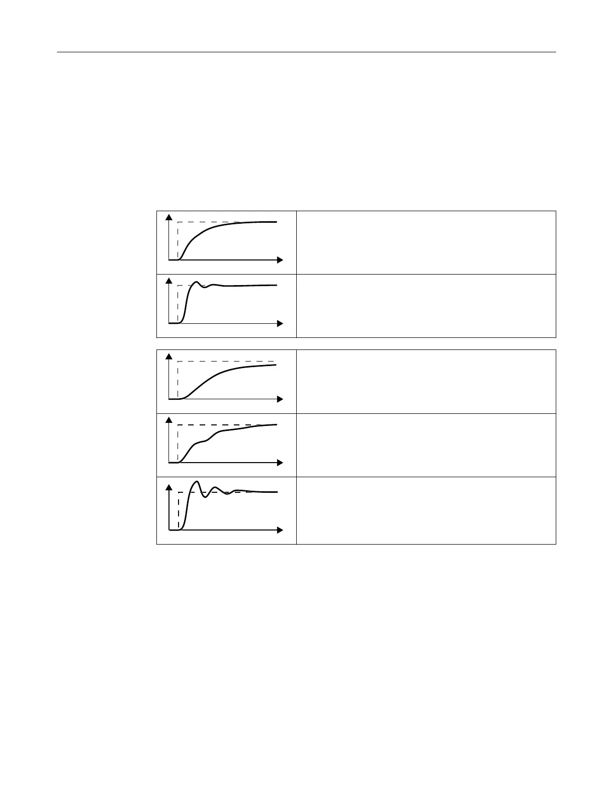
Optimum controller response for applications that do not permit
any overshoot.
The actual value approaches the setpoint without any signicant
overshoot.
Optimum controller behavior for fast correction and quick com‐
pensation of disturbance components.
The actual value approaches the setpoint and slightly over‐
shoots, maximum 10% of the setpoint step.
The actual value only slowly approaches the setpoint.
• Increase the proportional component K
P
(p2280) and reduce
the integration time T
I
(p2285).
The actual value only slowly approaches the setpoint with slight
oscillation.
• Increase the proportional component K
P
(p2280) and reduce
the rate time T
d
(p2274)
The actual value quickly approaches the setpoint, but overshoots
too much.
• Decrease the proportional component K
P
(p2280) and in‐
crease the integration time T
I
(p2285).
3. Set the ramp-up and ramp-down times of the ramp-function generator back to their original
value.
You have manually set the technology controller.
❒
Limiting the output of the technology controller
In the factory setting, the output of the technology controller is limited to ± maximum speed.
You must change this limit, depending on your particular application.
Example: The output of the technology controller supplies the speed setpoint for a pump.
The pump should only run in the positive direction.
Advanced commissioning
8.19PID technology controller
SINAMICS G120C Converters
Operating Instructions, 02/2023, FW V4.7 SP14, A5E34263257B AK 291
 Loading...


