/RDGWRUTXH0/
0RPHQWRILQHUWLD-
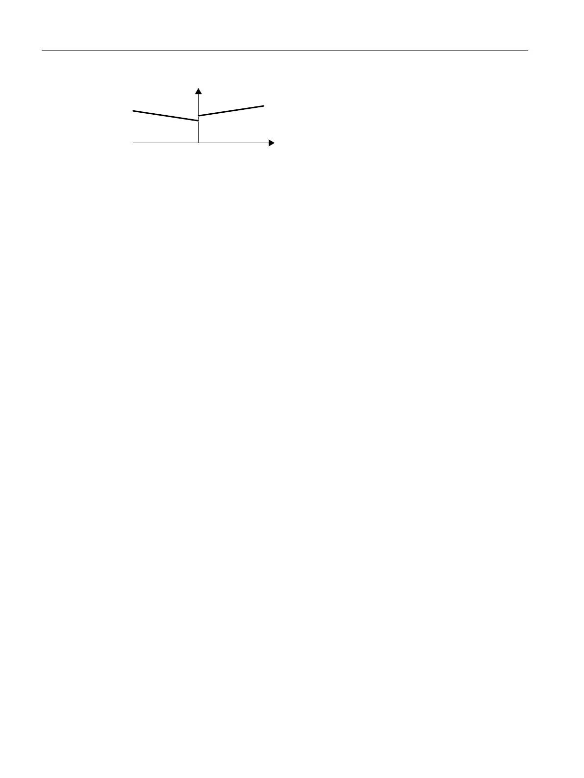
Figure8-60 Moment of inertia precontrol
The relationship between load torque and torque is saved in the converter as linear
characteristic.
• In a positive direction of rotation:
Moment of inertiaJ = p5312 × load torqueM
L
+ p5313
• In a negative direction of rotation:
Moment of inertiaJ = p5314 × load torqueM
L
+ p5315
You have the following options to determine the characteristic:
• You already know the characteristic from other measurements. In this case, you must set the
parameters to known values when commissioning the system.
• The converter iteratively determines the characteristic by performing measurements while
the motor is operational.
Activating the moment of inertia estimator
The moment of inertia estimator is deactivated in the factory setting. p1400.18= 0,
p1400.20=0, p1400.22=0.
If you performed the rotating measurement for the motor identication during quick
commissioning, we recommend leaving the moment of inertia estimator deactivated.
Requirements
• You have selected sensorless vector control.
• The load torque must be constant whilst the motor accelerates or brakes.
Typical of a constant load torque are conveyor applications and centrifuges, for example.
Fan applications, for example, are not permitted.
• The speed setpoint is free from superimposed unwanted signals.
• The motor and load are connected to each other with an interference t.
Drives with slip between the motor shaft and load are not permitted, e.g. as a result of loose
or worn belts.
If the preconditions are not met, you must not activate the moment of inertia estimator.
Procedure
1. Set p1400.18= 1
2. Check: p1496≠0
3. Activate the acceleration model of the speed controller pre-control: p1400.20=1.
You have activated the moment of inertia estimator.
❒
Advanced commissioning
8.20Motor control
SINAMICS G120C Converters
322 Operating Instructions, 02/2023, FW V4.7 SP14, A5E34263257B AK
 Loading...


