Home
Siemens
Inverter
SINAMICS G120C DP
Page 49
Siemens SINAMICS G120C DP - Page 49
478 pages
Manual
To Next Page
To Next Page
To Previous Page
To Previous Page
Loading...
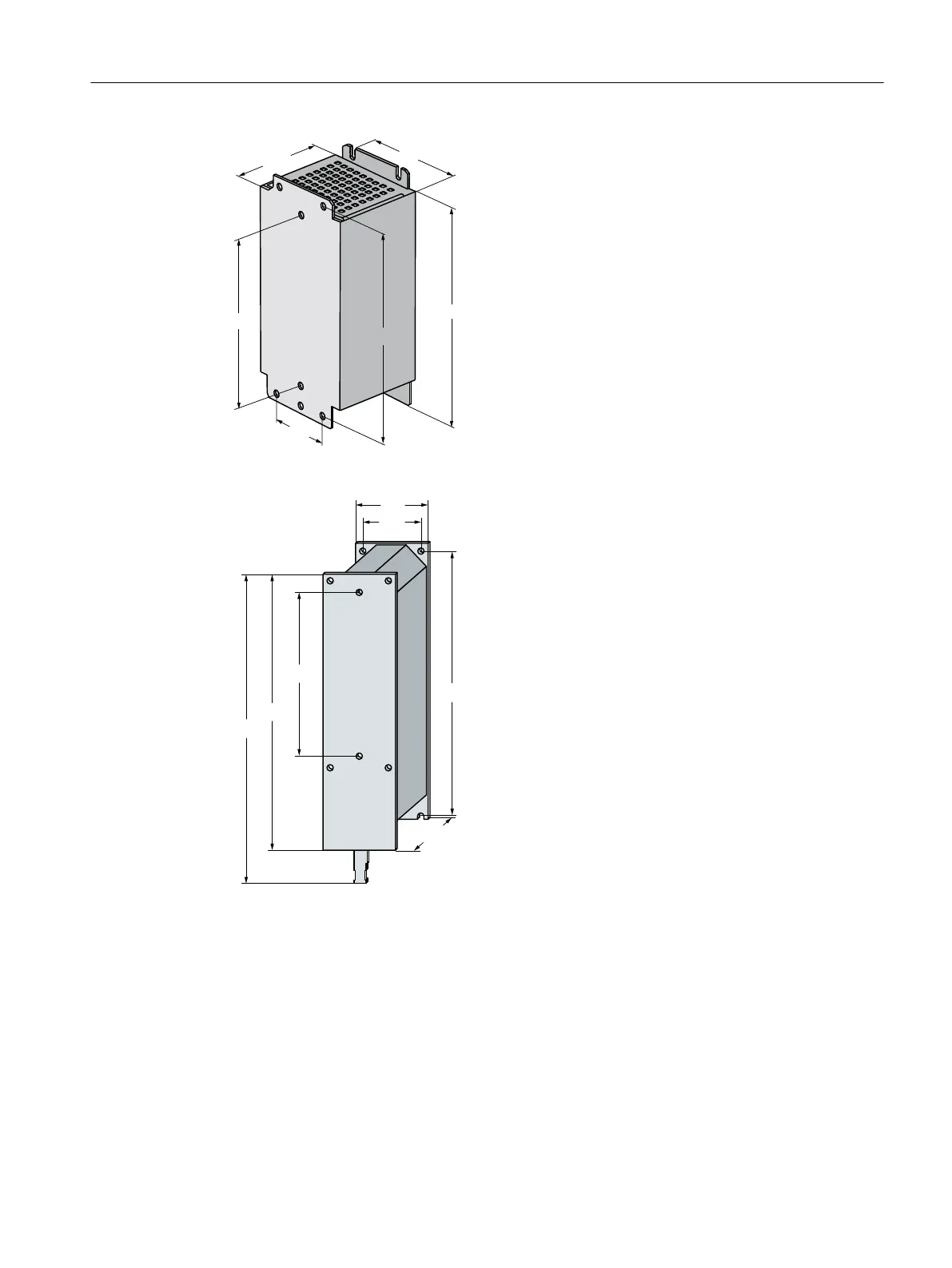
Figure4-8
Output react
or
Figure4-9
Sine-wav
e
lter
Installing
4.3Mounting base components
SINAMICS G120C Converters
Operating Instructions, 02/2023, FW V4.7 SP14, A5E34263257B AK
47
48
50
Table of Contents
Main Page
Changes in the Current Edition
5
Table of Contents
7
Fundamental Safety Instructions
15
General Safety Instructions
15
Equipment Damage Due to Electric Fields or Electrostatic Discharge
21
Warranty and Liability for Application Examples
21
Security Information
22
Residual Risks of Power Drive Systems
23
Introduction
25
About the Manual
25
Guide through the Manual
26
Description
29
Intended Use
29
Openssl
29
Transferring Openoss License Terms to a PC
29
Scope of Delivery Converters FSAA
30
Scope of Delivery Converters FSD
32
Directives and Standards
34
Optional Components
36
Motors and Multi-Motor Drives that Can be Operated
40
Installing
41
Installing the Label for the North American Market
41
EMC-Compliant Setup of the Machine or Plant
41
Control Cabinet
42
Cables
44
Electromechanical Components
47
Mounting Base Components
48
Mounting the Converter
51
Mounting the Line Reactor
58
Mounting the Output Reactor
60
Mount Du/Dt Filter Plus Voltage Peak Limiter
63
Mounting the Braking Resistor
64
Connect the Line Supply, Motor and Braking Resistor
66
Permissible Line Supplies
66
TN Line System
67
TT Line System
68
IT System
69
Requirements for the Protective Conductor
69
Installation after a Long Storage Time
71
Connecting the Converter and Converter Components to the Supply
72
Branch Circuit Protection
78
Operation with Residual Current Protective Device (RCD)
80
Maximum Permissible Motor Cable Length
82
Connecting the Motor to the Converter in a Star or Delta Connection
83
Connecting the Interfaces for the Converter Control
84
Overview of the Interfaces
84
Fieldbus Interface Assignment
86
Terminal Strips
87
Factory Setting of the Interfaces
91
Default Setting of the Interfaces
94
Failsafe Digital Input
103
Connecting a Failsafe Digital Input
105
Wiring Terminal Strips
107
Connecting the Cable Shields (FSAA
109
Connecting Cable Shields (FSD
110
Fieldbus Interfaces
111
Connecting the Converter to PROFINET
111
Communication Via PROFINET IO and Ethernet
111
Connecting the PROFINET Cable to the Converter
113
What Do You Have to Set for Communication Via PROFINET
113
Installing GSDML
114
Connecting the Converter to PROFIBUS
114
Connecting the PROFIBUS Cable to the Converter
115
What Do You Have to Set for Communication Via PROFIBUS
115
Installing the GSD
117
Set the PROFIBUS Address
117
Connecting a Motor Holding Brake
119
Monitoring the Temperature of the Braking Resistor
119
Commissioning
121
Commissioning Guidelines
121
Tools to Commission the Converter
122
Preparing for Commissioning
123
Collecting Motor Data
123
Converter Factory Setting
124
Minimum and Maximum Speed
125
Quick Commissioning Using the BOP-2 Operator Panel
126
Overview
127
Starting Quick Commissioning
128
Select the Application Class
128
Standard Drive Control
130
Dynamic Drive Control
132
Expert
135
Identifying the Motor Data and Optimizing the Closed-Loop Control
139
Quick Commissioning with a PC
140
Creating a Project
140
Transfer Converters Connected Via USB into the Project
141
Go Online and Start the Commissioning Wizard
142
Overview of Quick Commissioning
143
Commissioning Wizard
144
Standard Drive Control
146
Dynamic Drive Control
148
Expert
150
Identify Motor Data
153
Restoring the Factory Setting
155
Resetting the Safety Functions to the Factory Setting
156
Restore the Factory Settings (Without Safety Functions)
158
Series Commissioning
159
Handling the BOP 2 Operator Panel
160
Menu Structure, Symbols and Keys
160
Switching the Motor on and off
161
Changing Parameter Values
162
Changing Indexed Parameters
163
Entering the Parameter Number Directly
164
Entering the Parameter Value Directly
165
Why Can a Parameter Value Not be Changed
166
Uploading the Converter Settings
167
Why Does an Upload Make Sense
167
Uploading to the Memory Card
167
Recommended Memory Cards
167
Automatic Upload
168
Message for a Memory Card that Is Not Inserted
170
Manual Upload with Startdrive
170
Manual Upload with BOP-2
171
Safely Removing a Memory Card Using the BOP-2
172
Safely Remove the Memory Card with Startdrive
173
Uploading to the BOP-2
174
Upload to a PC Using Startdrive
175
More Options for the Upload
175
Protecting the Converter Settings
177
Write Protection
177
Know-How Protection
178
Extending the Exception List for Know-How Protection
182
Activating and Deactivating Know-How Protection
183
Advanced Commissioning
185
Overview of the Converter Functions
185
Brief Description of the Parameters
187
Sequence Control When Switching the Motor on and off
188
Adapt the Default Setting of the Terminal Strip
190
Digital Inputs
191
Analog Input as Digital Input
192
Failsafe Digital Inputs
192
Digital Outputs
194
Analog Input
196
Adjusting Characteristics for Analog Input
197
Setting the Deadband
199
Analog Output
200
Adjusting Characteristics for Analog Output
201
8.5 Controlling Clockwise and Counter-Clockwise Rotation Via Digital Inputs
202
Two-Wire Control, On/Reverse
204
Two-Wire Control, Clockwise/Counterclockwise Rotation 1
206
Two-Wire Control, Clockwise/Counterclockwise Rotation 2
208
Three-Wire Control, Enable/Clockwise/Counterclockwise Rotation
210
Three-Wire Control, Enable/On/Reverse
212
Drive Control Via PROFIBUS or PROFINET
213
Receive Data and Send Data
213
Telegrams
214
Parameter Channel
220
Examples
228
Expanding or Freely Interconnecting Telegrams
230
Device-To-Device Communication
233
Acyclically Reading and Writing Converter Parameters
233
Drive Control Via Modbus RTU
234
Drive Control Via USS
237
Drive Control Via Ethernet/Ip
240
Jogging
242
Limit Position Control
244
Switching over the Drive Control (Command Data Set)
245
Motor Holding Brake
247
Free Function Blocks
251
Selecting Physical Units
253
Motor Standard
253
Unit System
253
Technological Unit of the Technology Controller
255
Setting the System of Units and Technology Unit
256
Safe Torque off (STO) Safety Function
257
Where Are the Safety Functions Described
257
Principle of Operation
257
EMERGENCY SWITCHING off and EMERGENCY STOP
259
Commissioning STO
260
Commissioning Tools
260
Password
260
Configuring a Safety Function
262
Interconnecting the "STO Active" Signal
263
Signal Filter for STO Selection
264
Setting the Signal Filter for STO Selection
266
Forced Checking Procedure
266
Setting Forced Checking Procedure
267
Complete Commissioning
269
Checking the Assignment of the Digital Inputs
270
Acceptance Test
271
Setpoints
272
Overview
272
Analog Input as Setpoint Source
274
Specifying the Setpoint Via the Fieldbus
275
Motorized Potentiometer as Setpoint Source
276
Fixed Speed Setpoint as Setpoint Source
278
Setpoint Processing
281
Overview
281
Invert Setpoint
283
Inhibit Direction of Rotation
284
Skip Frequency Bands and Minimum Speed
285
Speed Limitation
287
Ramp-Function Generator
288
PID Technology Controller
291
Autotuning the PID Technology Controller
298
Motor Control
301
Reactor, Filter and Cable Resistance at the Converter Output
301
U/F Control
302
Optimizing Motor Starting
306
U/F Control with Standard Drive Control
307
Optimizing Motor Starting Using Standard Drive Control
310
Sensorless Vector Control
312
Structure of Vector Control Without Encoder (Sensorless)
312
Optimizing the Speed Controller
314
Advanced Settings
316
Friction Characteristic
318
Moment of Inertia Estimator
321
Application Examples for Closed-Loop Motor Control
326
Electrically Braking the Motor
326
Electrical Braking
326
DC Braking
328
Compound Braking
333
Dynamic Braking
334
Overcurrent Protection
338
Converter Protection Using Temperature Monitoring
339
Motor Protection with Temperature Sensor
342
Motor Protection by Calculating the Temperature
344
How Do I Achieve a Motor Overload Protection in Accordance with IEC/UL 61800-5-1
345
Motor and Converter Protection by Limiting the Voltage
346
Flying Restart - Switching on While the Motor Is Running
348
Automatic Restart
350
Kinetic Buffering (VDC Min Control)
352
Efficiency Optimization
354
Line Contactor Control
357
Calculating the Energy Saving for Fluid Flow Machines
359
Switchover between Different Settings
361
Alarms, Faults and System Messages
363
Operating States Indicated Via Leds
363
Identification & Maintenance Data (I&M)
367
Alarms, Alarm Buffer, and Alarm History
368
Faults, Alarm Buffer and Alarm History
371
List of Alarms and Faults
374
Corrective Maintenance
381
Replacing the Converter Hardware
382
Downloading the Converter Settings
384
Converter Without Enabled Safety Functions
384
Automatic Download from the Memory Card
384
Manual Downloading from the Memory Card with the BOP-2
385
Manual Download from the Memory Card Using Startdrive
386
Download from BOP-2 Operator Panel
387
Download from IOP-2 Operator Panel
388
Download from Smart Access
389
Download from the PC Using Startdrive
391
Converter with Enabled Safety Functions
392
Automatic Download from the Memory Card
392
Manual Downloading from the Memory Card with the BOP-2
393
Download from BOP-2 Operator Panel
395
Download from IOP-2 Operator Panel
396
Download from Smart Access
398
Download from the PC Using Startdrive
401
Download with Active Know-How Protection with Copy Protection
403
PROFINET Device Name
405
Spare Parts
405
Overview
405
Replace the Fan Unit for the Heat Sink
407
Replacing the Fan for FSD
408
Replacing the Roof-Mounted Fan
410
Firmware Upgrade and Downgrade
412
Overview
412
Preparing the Memory Card
413
Upgrading the Firmware
414
Firmware Downgrade
416
Correcting an Unsuccessful Firmware Upgrade or Downgrade
418
Reduced Acceptance after Component Replacement and Firmware Change
419
If the Converter no Longer Responds
420
Technical Data
423
Technical Data of Inputs and Outputs
423
High Overload and Low Overload
424
Overload Capability of the Converter
425
General Converter Technical Data
426
Technical Data Dependent on the Power
427
Data Regarding the Power Loss in Partial Load Operation
433
Current Reduction Depending on Pulse Frequency
434
Restrictions for Special Ambient Conditions
434
Electromagnetic Compatibility of the Converter
437
Harmonic Currents
441
EMC Limit Values in South Korea
441
Protecting Persons from Electromagnetic Fields
441
Accessories
442
Line Reactor
442
Line Filter
444
Output Reactor
445
Sine-Wave Filter
446
Du/Dt Filter Plus Voltage Peak Limiter
447
Braking Resistor
448
Appendix
451
New and Extended Functions
451
Firmware Version 4.7 SP14
451
Firmware Version 4.7 SP13
451
Firmware Version 4.7 SP10
453
Firmware Version 4.7 SP9
455
Firmware Version 4.7 SP6
457
Firmware Version 4.7 SP3
458
Firmware Version 4.7
460
Firmware Version 4.6 SP6
461
Firmware Version 4.6
462
Firmware Version 4.5
463
Interconnecting Signals in the Converter
463
Fundamentals
463
Application Example
465
Manuals and Technical Support
467
Overview of the Manuals
467
Other manuals for Siemens SINAMICS G120C DP
Manual
62 pages
Related product manuals
Siemens SINAMICS G120C
478 pages
Siemens SINAMICS G120C PN
478 pages
Siemens SINAMICS G120
732 pages
Siemens SINAMICS G120P
550 pages
Siemens SINAMICS G180
218 pages
Siemens SINAMICS V20
426 pages
Siemens SINAMICS V10
124 pages
Siemens Sinamics PM250
96 pages
Siemens SINAMICS V20 Inverter
66 pages
Siemens SIMODRIVE 611A
329 pages
Siemens Simovert P 6SE21 Series
34 pages
SIMOVERT MASTERDRIVES 6SE70 VC
57 pages