5. Place the seal on the cables to be connected.
6. Connect the cables in the converter.
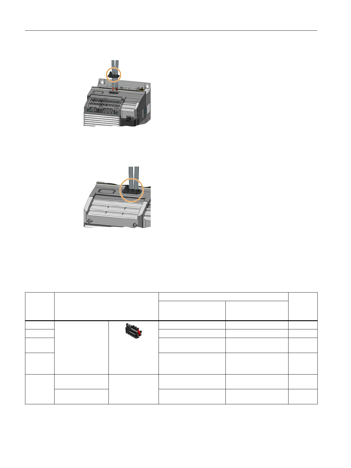
7. Push the seal into the converter housing.
8. Mount the upper converter cover.
You have connected the braking resistor.
❒
Conductor cross-sections and tightening torques of the converter
Table 4-6 Conductor cross-sections and tightening torques
Converter Connection Cross-section, tightening torque Stripped
insula‐
tion
length
Metric Imperial
FSAA, FSA Line system, motor
and braking resistor
Plug connector
with screw termi‐
nals
1…2.5mm
2
, 0.5Nm 18…14AWG, 4.5lbfin 8mm
FSB 4…6mm
2
, 0.6Nm 12…10AWG, 5.5lbfin 8mm
FSC,
11kW
6…16mm², 1.5Nm 10…5AWG, 13.5lbfin 10mm
FSC,
15kW …
18.5kW
10…16mm², 1.5Nm 7…5AWG, 13.5lbfin 10mm
FSD Line and motor Screw-type termi‐
nal
10…35mm
2
,
2.5…4.5Nm
8…2AWG, 22lbfin 18mm
Braking resistor 2.5…16mm
2
,
1.2…1.5Nm
20…6AWG, 15lbfin 10mm
Installing
4.9Connect the line supply, motor and braking resistor
SINAMICS G120C Converters
74 Operating Instructions, 02/2023, FW V4.7 SP14, A5E34263257B AK
 Loading...


